The Legend of EL PIPE-O
Kent English
Introduction
Most woofers just don’t quite do the lowest octave. You read the specs that say “usable response: 20 Hz – 20 KHz” and you know that the 20 Hz part of it is wildly optimistic. Achieving very low frequencies at reasonable power levels is not an easy job; the acoustic impedance experienced by a speaker cone declines as the inverse of the square of the frequency. As a practical matter, woofers and their enclosures need to be very large to properly reproduce the lowest octave. Even when you compensate with frequency equalization and more amplifier power, the performance suffers as you reach the excursion and power handling limitations of a small cone in a small box.
Let’s face it. Size does matter.
This is the saga of El Pipe-O, an adventure in over-the-edge woofer construction. The name El Pipe-O came from its striking resemblance to a legendary smoking appliance belonging to one of Pass’s roommates in college that was the object of worship by a small cult.
El Pipe-O consists of very large woofers mated to large cylindrical transmission lines. The goal is to get good powerful response down to 20 Hz at levels where the room starts to rattle before the loudspeaker.
Bass Reflex Enclosures
Suspended by elastic material, woofer cones have a natural fundamental resonant frequency at which the motion increases dramatically, and below which the response drops off at a sharp rate. Many woofer enclosures attempt to set up some sort of counter-resonance that
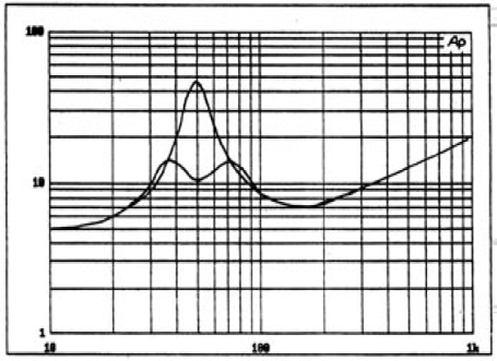
woofer reflects the motion of the cone, and here we see a comparison between the woofer’s impedance in free air versus its impedance in a tuned bass-reflex enclosure.
Pipe Dreams
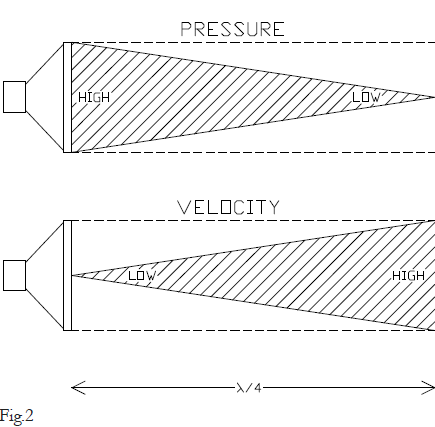
A transmission line is a different approach to achieving a similar effect. In any tube shaped object, closed at one end, a resonance develops at the frequency where the wavelength is four times the length of the tube. This effect is exploited in numerous musical instruments, particularly the pipe organ.
The wavelength of a frequency is the speed the wave travels divided by the frequency. For sound going through air, that speed is approximately 1100 feet per second. At 20 Hz, the wavelength is about 55 feet, and this is where a 14 foot tube will resonate.
With a loudspeaker mounted at one end of the tube, essentially closing off that end, the mass and elasticity of the air in the tube will cause a favored frequency where the tube is 1⁄4 the wavelength. In Figure 2 we see that at this frequency the pressure and air motion are 90 degrees
the apparent volume of the enclosure for a bass-reflex and the length of the enclosure for a transmission line. Choice of the density of this material is often left to the discretion of the constructor, which the instructions, “Stuff to taste.”
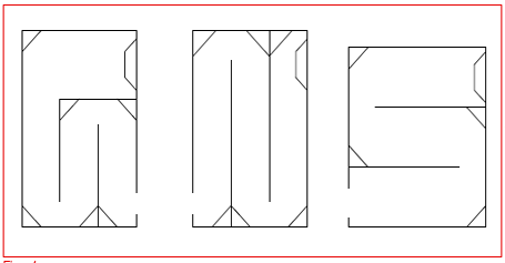
As with horns, the best transmission line is a straight one, with no bends. Bends compromise the effect, but often not so much that they still aren’t useful. Quite a few transmission lines have been designed which have bends in them in order to fit them into a reasonable space. Figure 4 shows a couple of examples. They work well, exhibiting only minor compromise. Our favorite configuration is where the rear wave exits at the rear near the floor. In this case, the floor adds some acoustic loading for greater output, and the opening is pointed away from the listener and is at some distance from the front of the woofer. This approach minimizes interaction between the woofer’s front and rear wave at higher frequencies and also effectively adds a little length to the line.
However, El Pipe-O is going to be a straight vertical tube, with the woofer(s) at the bottom and the open end of the pipe at the top. It is not going to fit in an 8 foot high listening room.
Enter the Sonotube
Of course we can built our transmission line any way we like out of wood, or those gigantic plastic storm drain type pipes, or even those monstrous concrete sewer pipes. Perhaps somewhere along the Alaskan pipeline is one happy audiophile, but we are going to do it the easy way; with Sonotubes.
is used to damp out this uncontrolled motion and turn it to getting a little more bass out of the speaker. The two most popular approaches are the bass-reflex enclosure and the transmission line.
The bass-reflex enclosure has the woofer mounted in a box that has a specific internal volume and an opening to the outside. Any box with an opening has its own acoustic resonance, known as Helmholtz resonance, which you experience when you blow into the opening of a beer bottle. Varying the volume of the box or the size of the opening (called the port) adjusts the frequency of resonance, and you can tune it to the same frequency as the resonance of the woofer.
When the box’s resonance is the same as the woofer’s resonance, you get an interesting effect: The woofer experiences acoustic loading which damps out its uncontrolled motion and the port delivers extra acoustic output to the outside world. The performance improves because the cone moves less and the output is boosted at the lowest frequencies. This can be seen in the impedance curves of figure 1. The impedance of the
out of phase with each other, so that high pressure develops at the closed end where motion is not favored, and high air motion occurs at the open end, where it can flow easily to the outside and no wall favors the buildup of air pressure.
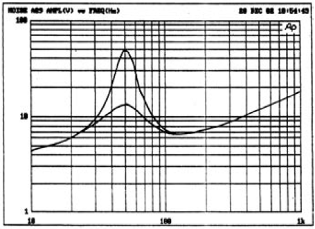
This resonance is similar to that of the bass-reflex enclosure, and it has a similar effect. Figure 3 shows the impedance of a woofer in free air and in a transmission line tube tuned to the resonant frequency. Like the bass-reflex, the transmission line damps out the resonant motion of the cone, but it does it with a lower “Q”, or sharpness, so that you tend to get a single bump instead of the double bump of Figure 1. Also like the bass-reflex, the output from the opening delivers more acoustic energy to the room, extending the response and power at the lowest frequencies.
Personally we favor a well-done transmission line over a bass-reflex enclosure. The bass is tighter and less boomy, It also tends to extend deeper. Part of this effect comes from the actual lowering of the resonant frequency of the woofer due to the additional air mass it has to push in the pipe.
You can adjust the “Q” or sharpness of both the bass-reflex and transmission line enclosures by stuffing them with wool, Dacron, or fiberglass. The more fibrous material you put in them, the more damped the effect. Resistive material of this sort also tends to increase
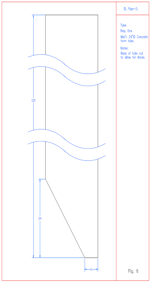
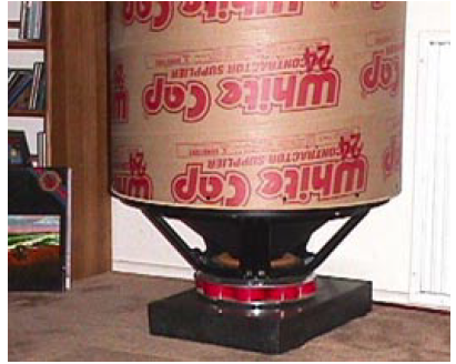
Sonotubes are heavy duty cardboard-type tubing used to cast concrete into pillars. They are available in a number of diameters and lengths, and are generally available in metropolitan areas. We usually buy them at White Cap stores, and we have played with 8 inch, 14 inch, and 24 inch diameters. We get them in 12 foot lengths, and the store will usually cut them to a desired length. If not, they, they are easy to cut with a saber saw. Oh yeah, and they are pretty cheap.
Because they are cylindrical in shape, the tubes are very strong, like eggs, for pressure which is equal around the circumference of the tube, which is what they will experience in a transmission line. Also, the fiber material comprising the walls is dense and fairly dead acoustically, making them a good choice.
For this project we bought a pair of 12 foot long, 24 inch diameter Sonotubes.
The Woofers
If you read the MCM catalog ( www.mcmelectronics.com ) then you’ve undoubtedly seen them. Part # 55-1835, Twenty-one inch Low Frequency Pro Woofer. Eight ohms, 96 dB at 1 watt, 25 Hz resonance, 200 watts rms, 800 watts peak. Price: $395.
Pass couldn’t help himself and bought four of them. They sat around for a couple of years in boxes until we decided to make El Pipe-O. In fact, El Pipe-O was the excuse to use them up. They look to be copies of a large Focal woofer, but the manufacturing quality is not quite as high. If you buy these, we recommend that you test them right away for voice coil mis-alignment. You can do this by pumping a low frequency signal into them while listening for scraping.
Construction
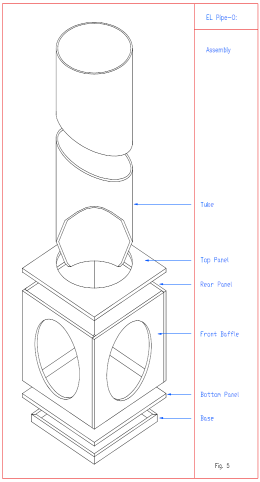
We decided to use two woofers per side to maximize the cone surface area and power handling of each speaker. Boxes were constructed of MDF so that the woofers were mounted on adjacent sides and the sonotubes were inserted from the top and were supported on the floor
Intro
of the box, with the sonotubes truncated at an angle that provided a good opening between the tube and the box.
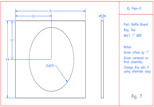
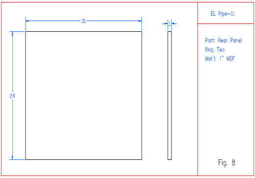
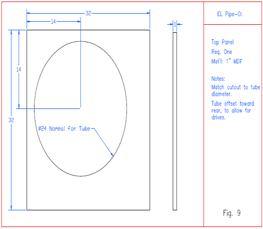
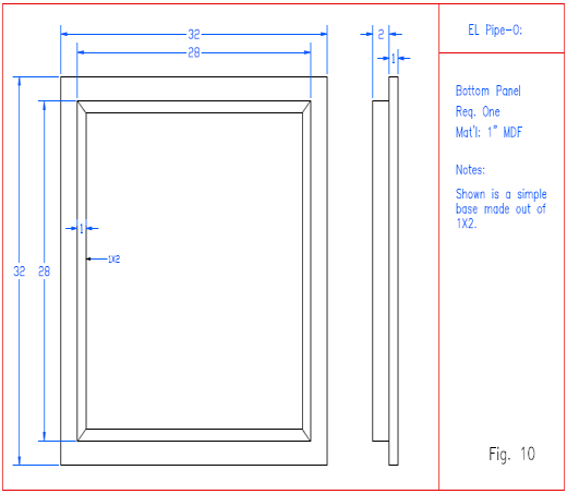
Figures 5 through 10 provide details of the construction and dimensioning of the boxes and cuts. The usual speaker construction techniques are appropriate, including the use of bracing and sealing materials.
Because of the size and weight of the speakers, final construction occurred at the spot where they were to be used. The tubes were mounted and glued in place at the
box opening and on the box floor, and silicone sealant was used around the juncture of box and tube. The woofers were wired in parallel, to form 4 ohm loads on each channel. The box was filled loosely with Dacron prior to mounting the woofers, and the woofers were mounted using lag bolts and string caulk.
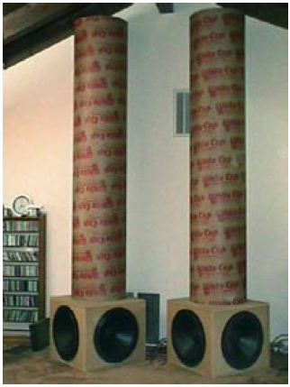
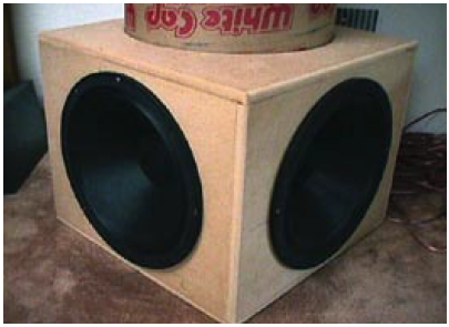
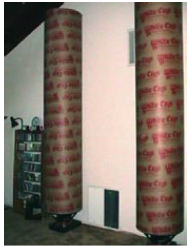
Finally the tubes themselves were filled with 20 lbs of Dacron each. Figures 11 and 12 are photographs of the finished speakers.
Performance
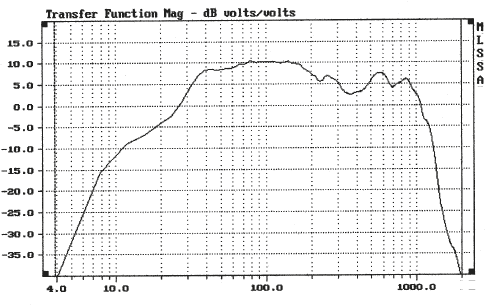
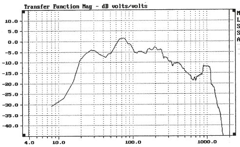
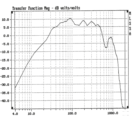
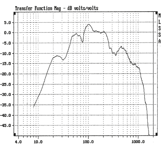
Figure 13 shows the near field response curve of the drivers without equalization or crossover filters, driven at 1 watt (2.83 volts). Figure 14 shows the response curve of El Pipe-O at 1 meter away, where room effects can start to be observed. Both curves are calibrated so that 0 equals a 100 dB level.
Like many big woofers, the response curve extends out to higher frequencies irregularly and with questionable transient response. Also seen in the curves is the need for some equalization to make the woofer truly flat down to 20 Hz. No problem, we will simply make a crossover filter that accomplishes both requirements.
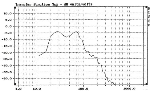
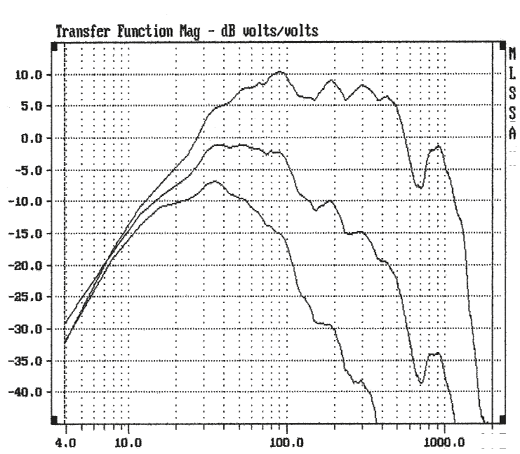
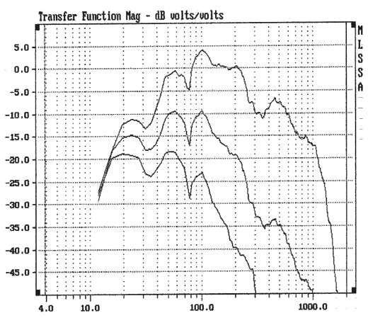
Using a Pass XVR1 we set up, measured, and listened to a wide variety of possible crossover filters; varying frequency, slope, and Q. Ultimately we settled on a 2 pole, 22 Hz low pass filter as the best sounding compromise. Figure 15 shows the near field response with no filter, 1 pole low pass (6 dB/octave) at 22 Hz, and the 2 pole low pass (12 dB/octave) that we ended up using. Figure 16 shows the response at 1 meter. Note that active filtering does not alter the sensitivity of the loudspeaker, which ranges from about 85 to 103 dB / watt.
Pass’s listening room measures 30 ft by 30 ft, with a 14 foot ceiling at the center. The height of El Pipe-O at 12 feet mean that we were not able to play with corner placement, and we placed the speakers a few feet apart just behind where speakers would ordinarily be placed, and allowing about 2 feet space between the pipe openings and the ceiling.
The final result (bottom curve) measures about +-3B
Intro
in the room from about 13 Hz to 75 Hz, and it goes away rapidly enough at higher frequencies to avoid being obnoxious. We evaluated the performance in systems using the Fostex 204 “full range” speaker, the TAD1101 with a Raven R2 on the top, and (over time) a fairly wide sampling of conventional speakers, none of which had a particularly strong bottom end.
A very important consideration is the quality of transition from subwoofer to an ordinary woofer; the phase and amplitude of the mixed response has to be smooth or it can sound pretty awful. If these aren’t right, the bass can get very boomy from peaks or suffer frequency drop-outs that destroy the attack.
Fortunately, El Pipe-O “plays well with others” as long as there is not too much distance between the big woofers and the higher frequency drivers. We found that placing the main speakers directly in front of the transmission lines worked best.
Active Crossover
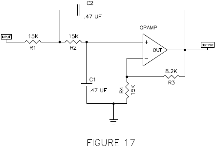
Figure 17 shows an active op-amp type circuit that delivers the crossover filter characteristic we used, which is a 2 pole low pass at 22 Hz. The tolerances are not at all critical, and just about any ordinary high quality gain circuit will do.
around 20 Hz.
Movie soundtracks are a good source of this sort of thing: Jurassic Park or Dracula. Pink Floyd’s Dark Side of the Moon. You know what kind of records we’re talking about.
Funny things happen when your speakers are flat to 13 Hz. You have to be careful about your tone arm, your windows, your neighbors, and your bowels. After we got the system running, we spent a hour or so going around the room bolting down or otherwise re-arranging knick-knacks, shelving, furniture and windows that began rattling. After that, we called up our friends and had a little party. And another.
The Party Incident
The first listening sessions were run with 100 watt amplifiers. Of course something like El Pipe-O calls for monster amplifiers, so we acquired Pass X1000’s, which can do about 4,000 watts peak (per channel) into 4 ohms. The occasion of firing these up called for another party, during which we drank a lot of Cabernet and then decided to test the power handling claims of the woofer manufacturer.
These claims were fairly accurate at 800 watts peak
coupler, we placed some of the kind of plastic grid used in elevator lights to keep the dacron from falling onto the woofer cones. The tubes were stuffed the same, and we used the same crossover filter.
Figure 22 shows the near field output of the single woofer without the filters, which actually turned out a bit flatter than the twin driver models. Moving out into the room at two meters we get Figure 23, and applying the filter we get Figure 24. Noting the differences between the twin and single woofer versions, we see that the single woofer gives flatter response at frequencies above 20 Hz, but falls off more quickly below 20 Hz. Nevertheless it manages a respectable +-2 dB from 20 to 80 Hz.
The reconstructed version sounded about as good as the original, and probably gives a smoother transition to other speakers. It doesn’t have quite the same power handling and doesn’t go quite as low, but in our opinion, it ended up being a slightly more elegant result.
Conclusion
Except for the sheer scale of the endeavor, this was a remarkably easy project. Sonotubes make great transmission lines, and the vertical floor to ceiling approach is simple and effective. They might be tall, but the footprint is small, and maybe your wife will let you keep them if you finish them properly. If you have an 8 foot ceiling, you can make two out of a 12 foot piece of 8 inch diameter, and find yourself decent 8 inch woofers resonant at about 40 Hz. Then you can start having parties, too.
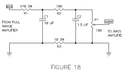
Passive Active Crossover
Figure 18 shows a “passive” circuit which is designed to be placed at the output of the amplifier driving the main speakers which filters and attenuates that signal for feeding to the amplifier(s) driving El Pipe-O. As with the active filter, the tolerances and such are not particularly critical, but note that this circuit is not designed to be driven by an amplifier with balanced outputs, where both output connections are “live”. It assumes the amplifier (-) connection is at ground, and also assumes that the ground of the driving amplifier and the ground of the bass amplifier are at similar potentials (which they usually are). If you wish to build just one El Pipe-O for both channels, you can give each of the two woofers its own crossover and amplifier, or you can mix inputs at the input of the crossover, giving each channel its own input resistor with twice the resistance value shown in Figure 18.
The Sound
Well, of course this is the best part. First you have to go through your record collection looking for material that goes down this low. A lot of nice sounding music doesn’t go below 40 Hz or so, and if you listen to this material, you don’t really get the impression that anything particularly special is happening.
This is good, because we didn’t want the speaker to offer up a freak show of special effects where it’s not wanted; we want neutral and seamless performance in the upper bass. No, we wanted the freak show to be down
each, and at the end of this event we were down to two woofers.
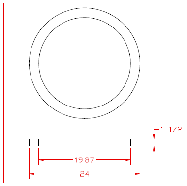
Reconstruction
Rather than spend another $800 on woofers, we decided to try single woofers on each side, so we took apart the tubes and reconfigured them as 10 foot tubes with a woofer at the bottom. We made a nice cylindrical coupler out of MDF to mate the woofer to the tube (Figure 19) and sat them on the woofer’s magnet on blocks of granite (Figures 20 and 21). On top of the