Zen Variations 6
Nelson Pass
Introduction
U.S. Patent # 5,376,899 describes an amplifying circuit topology that takes advantage of the character of matched balanced amplifiers that are cross-coupled to provide cancellation of distortion and noise. The result provides high performance with very simple linear circuits and has been dubbed Super-Symmetry, an homage to particle physics, and is also known popularly as the X circuit. Super-Symmetry works by exploiting the complementary characteristics of matched balanced circuits to differentially reject distortion and noise, and applies a small amount of feedback to extend this symmetry, making the distortion and noise even more identical on each half of a balanced amplifying circuit.
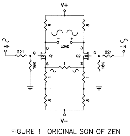
In this article we are going to apply this technique to a previous project, the Son of Zen (Audio Electronics 2/97) which can also be found at www.passdiy.com and whose schematic is shown in Figure 1. Here we see a very simple single stage balanced differential amplifier without feedback or capacitors. Balanced input signal is presented to the + and – inputs, and a larger version of that balanced signal occurs across the output load.
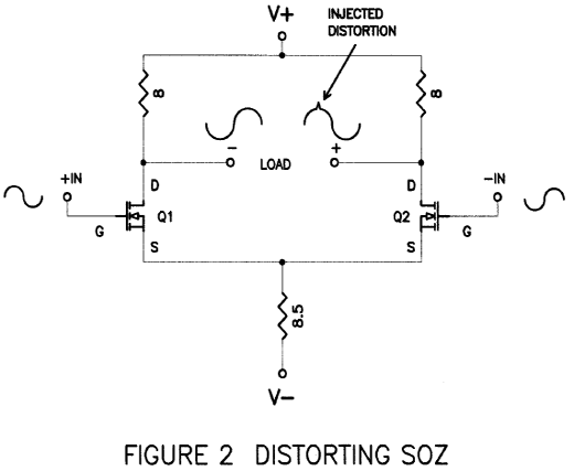
To best understand Super-Symmetric feedback, we start by considering Figure 2, where a simplified version of the Son of Zen is shown and where we arbitrarily inject a positive blip representing distortion or noise on the positive output. Because the SOZ amplifier has no feedback of any sort, there is no correction for this and it appears across the load.
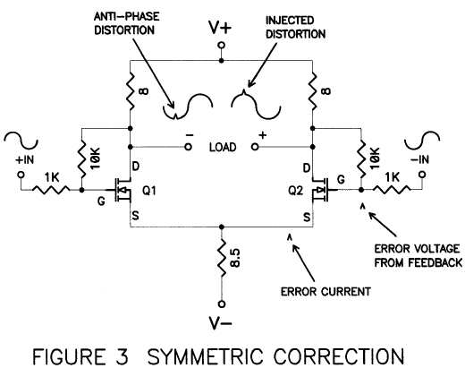
Figure 3 shows the addition of two symmetric feedback loops to the circuit of Figure 2, consisting on 1 Kohm resistors in series with the inputs, and 10 Kohm resistors connecting the input Gates of the Mosfets to the output Drains, forming a local feedback loop for each transistor.
If we arbitrarily inject a blip of distortion into the output of Q2 as we did with Figure 2, we note that this blip will also appear (reduced in size) at the Gate of Q2, and as a result will also appear as a blip of current coming out of the Source of Q2. This current blip drives the Source of Q1, and makes the blip appear on the Drain of Q1, in phase with the blip on the Drain of Q2. To the extent that the sizes and timing of the two blips are identical, they cancel, and are not seen by the load, which is to say they disappear from the standpoint of the loudspeaker.
The unique thing about this arrangement is that the distortion contributed by each half of the amplifier appears nearly equally in phase at both outputs, but the signal appears out of phase at the outputs. So the desired signal is reinforced and the undesired noise and distortion is cancelled.
Super-Symmetry is ideally used to obtain high quality performance from very simple circuit topologies, avoiding the high order distortion character and feedback instabilities of complex circuits.
A single-stage circuit, such as the SOZ would not actually be expected to see as much improvement as a two-stage circuit because by it’s very nature, it does not correct for the non-linearities in output current caused by the Gate-to-Source non-linearities of the differential pair themselves. This is a fundamental limitation, and of course is true of differential pairs in general.
However Super-Symmetry does correct the errors in the parts of the circuits that follow them. In a two or three gain stage design, the differential pair corrects the errors of the 2nd and 3rd stage, and of course any non-linearities in the output voltage contributed by the loudspeaker. Typically a two gain stage version of this topology can outperform the three or more stages of a conventional amplifier. By gain stages, I generally mean how many transistors there are in series with the signal path, ignoring cascode transistors and counting complementary pairs as a single stage.
As a demonstration of the power of this approach, Pass Labs launched the first “X” amplifier, the X1000, as a 2 stage design with a small amount of feedback, delivering over 1000 watts with high performance. It has compared well against amplifiers having as many as 9 sequential gain stages, and as of this writing is still in production.
The X feedback technique works less well with many gain stages and high open loop gains, mostly because the transit delays through complex circuits can cause a “hall of mirrors” effect, where the correction comes too late and the distortion bounces back and forth in the circuit. Ordinary feedback amplifiers suffer pretty much the same fate, unless they are deliberately slowed down by frequency compensation.
Why is this important? Because there is a different character of sound attributed to simple linear circuit topologies versus the complex circuits that obtain their
performance through the generous use of feedback. It is difficult to produce high power amplifiers with simple circuits, and many previous efforts using many gain stages and high feedback have been described as powerful but musically clinical. Super-Symmetry makes it easier to produce high power amplifiers with the musical characteristic of simple low power amplifiers.
Construction
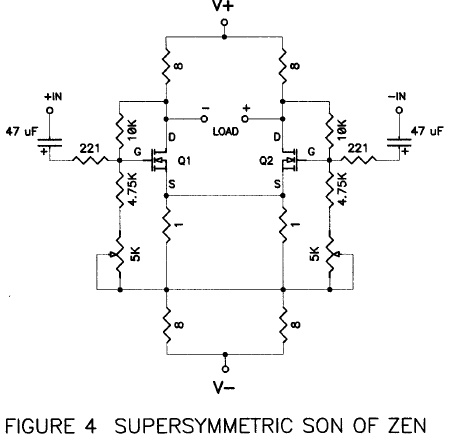
Figure 4 shows the actual circuit that has been modified from the original SOZ. All the details of the original project apply to this amp, and I refer you to that article. We see that the 1 ohm resistor has been removed between the Sources of Q1 and Q2, and we see the addition of two input capacitors of arbitrary value, 1 Kohm input and 10 Kohm feedback resistors, which set the gain of the circuit. Also 4.75 Kohm resistors in series with 5 Kohm pots are used to set the operating point of the Mosfets precisely for best performance. I will refer to this circuit hereafter as the SOX for brevity.
Performance
In order to properly assess the differences between the original SOZ and one with the addition of symmetric feedback, I built a SOZ channel, made the appropriate measurements, and then removed the 1 ohm Source to Source resistor and added the feedback elements to form the circuit of Figure 4. To compare apples to apples, I used the same supply, the same transistors, an identical layout and test setup, and the bias current and gain was designed to be identical. The power supply consisted of a CLC network of 30,000 uF, 2 mH, and 30,000 uF for each rail polarity. Again, other details of the circuit are to be found in the original Son of Zen article.
A single stage is the best for tutorial examples, but is not otherwise the most ideal example of the power of Super-Symmetry. Nevertheless some interesting and nonintuitive results were achieved.
Unless otherwise noted, the curves and data that follow were with an 8 ohm resistive load, Frequencies at 1 KHz, Output levels at 2 watts, 600 ohm balanced source or 50 ohm single-ended source, and either +/- 30 Volt @ 6 amps total bias or +/- 40 Volts at 8 amps. (6 amps bias means 3 amps through Q1 and Q2 each).
In the cases where the rails are at +/- 30 Volts, the Drain voltages of the SOX circuit were set on what I judged to be optimal at 8 Volts referenced to ground, which was also about 12.5 volts Drain-Source. For the +/- 40 Volt case, the Drain voltage was set at 8.6 Volts DC referenced to ground, which was 13.7 Volts Drain-Source on the Mosfets.
As previously noted, the SOZ and SOX gain figures were set about the same, which is close to 12 dB with an 8 ohm load. The offset potentiometers were set to the get the desired Drain voltages with a difference of less than 50 mV DC, which is then the DC offset experienced by the load. This should be re-adjusted after adequate warm-up, as the character of the Mosfets drifts with temperature.
First off, I measured the open loop gain without feedback (and without the 1 ohm resistor Source-Source) and got a figure of about 20 dB. With a 12 dB gain after the application of feedback, we calculate 8 dB of feedback on the amplifier.
I measured the damping factor, which was about .5 (16 ohm output impedance) for the SOZ and about 3 (2.7 ohm output impedance) for the SOX, which is an improvement by a factor of 6 times, more than twice what we would expect with 8 dB of feedback, a good example of the power of Super-Symmetry.
The input impedance of the SOZ was whatever you set the input-ground resistors and the capacitance of the Mosfets. After the addition of the feedback loops the SOX input impedance measures approximately 4 Kohms balanced and 2 Kohms unbalanced. This figure is approximate, as it depends somewhat on the Mosfets and the other settings. It’s not a high figure, and it can easily be raised to higher values by increasing the input network values proportionately, but at a cost of higher distortion at high frequencies. Alternatively, you can simply raise the value of the 1 Kohm input resistor if you can afford to throw away some gain. In my experience, it will work well with any balanced source, and most single-ended sources, but there are some tube circuits out there that won’t like it.
As before, there is no frequency compensation in the amplifier, and I have not encountered a case of instability over the years. It will drive anything, maybe not well, but without oscillation. You can short the outputs as you like, it will not damage the amp. I have not seen significant turn on/off thumps, and I don’t expect you to. The amplifier benefits from Vgs matched transistors, but they are not required.
You can refer to the dissipation and power figures from the original SOZ article, and after the modification, the output power goes slightly higher for a given supply level, as there is no longer the loss across the 1 ohm Source-Source resistor of the differential transistors, but otherwise the curves are very similar.
Distortion versus Amplitude at 1 KHz, 8 ohms
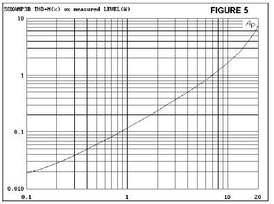
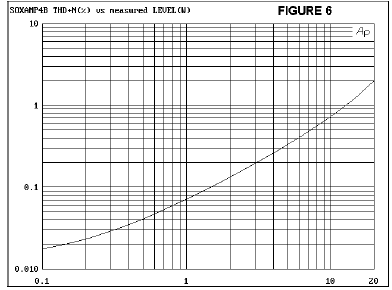
Figure 5 shows the distortion versus amplitude for the SOX circuit using 30 Volt rails and a balanced 600 ohm source. From the curves I would call this a 10 watt amplifier. Figure 6 shows the same for 40 Volt rails, and I would call this a 20 watt amplifier. For both cases, the overall efficiency is about 3%. It’s pretty clear that the higher voltage and bias of the latter gives marked improvement. In both cases we see a small improvement over the SOZ, but nothing to write home to mom about. As pointed out earlier, we do not expect improvement in this regard at lower frequencies because for a single stage amplifier, Super-Symmetric feedback does not correct the Vgs versus current distortion of the first differential pair, and that is mostly what we are measuring here.
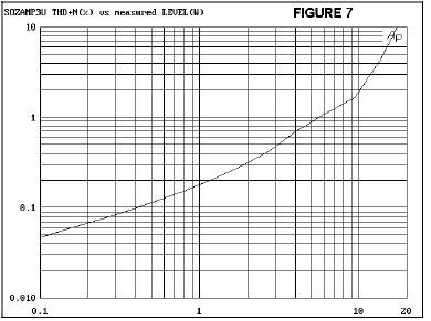
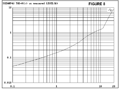
Distortion versus Amplitude – Single-Ended Source
The situation alters when the amplifier is driven from a single-ended source (and the minus input of the amplifier is grounded). The curves for the SOX amplifier do not change significantly, but we see that the distortion character for the original SOZ have roughly twice the distortion and begin clipping earlier. Figure 7 shows the 30 volt supply example of the SOZ and Figure 8 shows the 40 volt example.
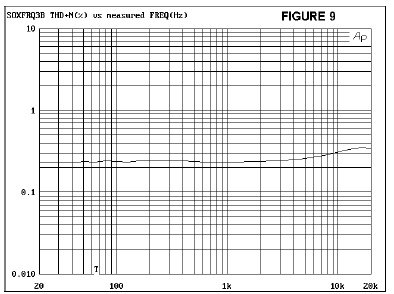
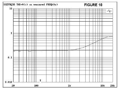
Distortion versus Frequency – Balanced Source
For the SOX circuit we see a slight increase in distortion (about twice) as we approach 20 KHz at two watts (Figure 9), and for the SOZ we see a more dramatic climb (Figure 10). I have not explored this difference thoroughly, but I am assuming that the feedback in SOX is removing device distortion outside of the Vgs/current effect, most likely the non-linearity in capacitances between the Drain-Source and Drain-Gate.
Distortion versus Frequency – Single-Ended Source
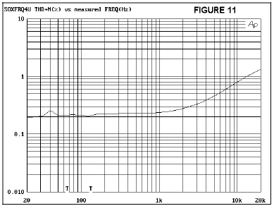
Figure 11 shows the increases that occur in distortion versus frequency in SOX when driven by a single-ended source. It goes up quite a bit toward 20 KHz, but less than half that of SOZ. We can use balanced sources here, or we can console ourselves that musical material declines in energy above 5 KHz.
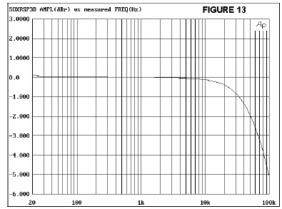
Frequency Response
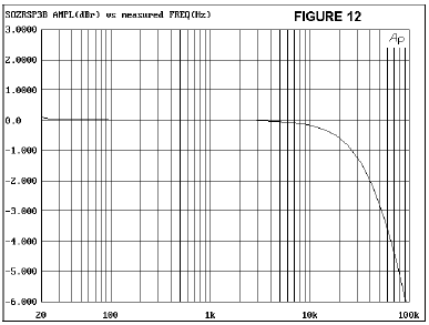
The high frequency roll-off for both SOZ and SOX do not alter appreciably for different supply voltages and bias currents, but the SOX does come out a faster, with a -3dB point at 70 KHz versus 50 KHz on the SOZ (Figures 12 and 13). These figures are unaffected by the use of balanced versus unbalanced inputs.
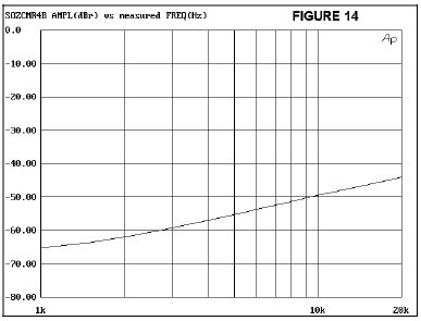
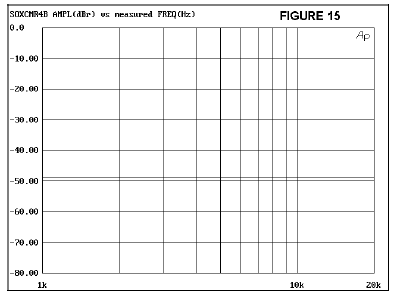
Common Mode Rejection
Both circuits show excellent input common mode rejection (CMRR), the ability to ignore noise appearing the same on both balanced inputs. The SOZ was slightly better (-65 dB) at low frequencies, but declined at high frequencies, while the SOX was about –50 dB, but constant across the audio band (Figures 14 and 15).
Listening Tests
When your output power is 20 watts with an efficiency of 3%, you tend toward the more efficient type of loudspeakers. Fine, that’s what I prefer anyway. I spent some quality time with the SOX and several drivers mounted in the J-Low rear loaded horns. (J-Low project, Audio Express (Feb, 2004), also at www.passdiy.com . The drivers were the Jordan 92, Manger, Fostex FE208 Sigma, and the Lowther DX55 with the “shower head” phase plug. The Manger and Jordan are not that efficient compared to the Fostex and Lowther, but all are interesting examples of single full-range drivers, particularly when augmented by a bass horn.
I don’t want to get into the relative merits of the drivers here (I will elsewhere), but I did compare these to the stock SOZ (actually the same amps, reconfigured), a pair of balanced Zen Lite (with the 3 bulbs) and the Aleph 30.
Previously, I had preferred the Aleph 30 on all the drivers except the Jordan, where the Zen Lite (Zen Variations Part 1, Audio Express, March 2002) sounded a little more musical. Part of this is that the other drivers, in spite of their varying efficiency, have larger cone areas and can make more use of the greater power of the Aleph 30. Previously the SOZ sat somewhere in between the other two amps. I rather expected to hear improvement in bottom end control and a more even spectral balance from the SOX. Maybe it’s a self-fulfilling prophecy, but that’s pretty much what I got.
Compared to the SOZ, definitely cleaner bottom and top, and more ability with complex music, particularly orchestral. If it was just a piano or vocal alone, the difference was not as great. I heard a bit better spectral balance in general, and the result was more musical and toe-tapping.
The most interesting experience, where the amplifier seemed outstanding, was with the Lowther on piano, material with dominant vocals and not much else, or string quartets (Philip Glass recordings, as an example). You could kill an evening pretty easily with this if you didn’t try to play it too loud or expect deep bottom end.
Compared to the Zen Lite, it depended on the bias conditions. I used a Variac to go between the two 30V and 40V settings, and at the higher bias, it definitely was better than Zen Lite and approached the Aleph 30 for dynamic range, and I would say matched it overall on most material. Unfortunately, at 40 volt rails and 4 amps bias per transistor (640 watts/ch dissipation), it ran hot as hell, and my heat sinking was not up to the job over long periods. As a result, quite a bit of the time was spent at the lower settings. Alas, the lower setting is slightly inferior, and it’s quite easy to get spoiled. This was true of the original SOZ as well, so some things just don’t change.
An argument is often made that amplifiers like this are wasteful of energy and not environmentally friendly. Well that’s true, but I get more enjoyment out an amplifier like this than driving a car, which consumes between 10 and 100 times more power. According to my electric bill, for the couple hours I might I spend listening each day, an amp like this represents about 2% of my overall consumption. I think I would not leave it on 24 hours a day, though.
To sum up, I am very happy with the results here. If you have already built a Son of Zen, then I certainly recommend that you run out and buy about 10 dollars worth of parts and upgrade it. If you haven’t already built a Son of Zen, stay tuned, and we’ll see about raising that efficiency figure real soon now.
Copyright 2004 Pass Labs, Inc.
“Aleph”, “Super-Symmetry”, and “Zen” are trademarks of Pass Laboratories, Inc.