Zen Variations 8
Nelson Pass
Introduction
Thanks to a nice person on the Pass Labs Forum ( www.diyaudio.com ), I became aware that high current power JFET transistors are again available. You can check them out at www.lovoltech.com which offers a small variety of high current N-channel vertical JFETs in TO-251 and TO-252 packages. They don’t hold a lot of voltage 20-24 volts) or dissipate lot of power (69 watts, derated at 1.8 watts/degree), but they do deliver up to 100 amps peak. Clearly designed as switches, they nevertheless offer a linear operating region and are attractive for audio amplifier design.
Small signal JFETs are routinely used in the input stages of the finest solid-state amplifiers and preamplifiers, where they give very high input impedance, high linearity, and very low noise. JFETs are routinely extolled in promotional literature for their “tube-like” qualities. Their characteristic curves, like MOSFETs, largely resemble pentodes.
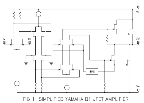
In the 1970’s, Sony and Yamaha offered a few JFET power amplifiers, but discontinued them for unknown reasons. Figure 1 shows a simplified schematic of the Yamaha B1, remains a highly regarded product.
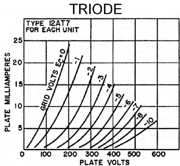
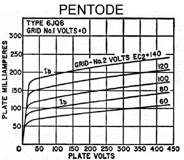
Why power JFETs you ask? Don’t we have enough transistors already? We do have lots of choices in devices, but a vertical JFET brings some particular characteristics to the table that we don’t get elsewhere. When we look at characteristic curves for devices we see what I would call the “triode character” and the “pentode character”, as illustrated in Figure 2.
FIG.2 TRIODE AND PENTODE CHARACTER
Here we see that the triode character has an partially exponential curve of current versus voltage across the device, while the pentode has a more logarithmic shape. You could think of the triode as “concave” and the pentode as “convex”, and by comparison, a resistor would have a straight line.
Since no gain device does such a good job of approximating a resistor, triode designers linearize the tube circuit by operating the voltage/current load line so as to get some cancellation between competing voltage and current distortion. This can be done with either single-ended or push-pull circuits.
The guys with pentode type devices, which includes solid state as well as nontriode tubes, take a different approach, which is to try to work them in the more voltage-invariant area and use other methods to correct for remaining nonlinearities, usually through negative feedback.
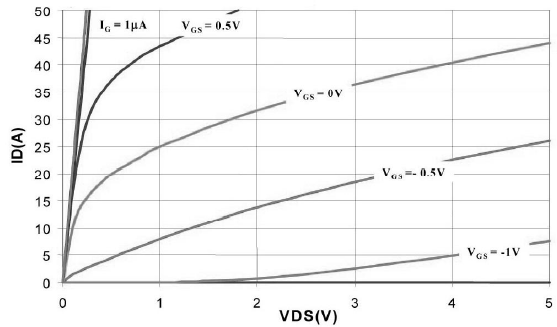
I’m not here to argue the merits of one approach over another, but as I look at the characteristic lines for these new power JFETs I notice that there is a narrow region at the bottom where there is less convex curvature. In fact it looks concave, kind of like a triode.
FIG.3 LU1014
In the case of JFET part LU1014, we note that with a gate voltage of –1 volt, the curve is concave below about 5 amps and 4 volts. In this range it has that triode character, and this is the area of interest to us here.
There are some other potential advantages to these JFETs. For a given bias current, they are more linear than comparable MOSFETs, and while they have comparable capacitances, the values are more linear over the operating voltages. Depletion mode is convenient, as it offers self-biasing with no particular circuitry to set the bias point, and the devices have a small negative temperature coefficient, so they hold a stable bias point easily. Last but not least, JFETs are not sensitive to static discharge,
The Single Approach
If we have a device that behaves a bit like a triode, then it is natural to try it out in a popular triode amplifier topology. For many aficionados that topology would be single-ended Class A operation. 300B’s and 211’s operated single-ended and coupled to an output transformer have been held by many as a low power musical standard. Single-Ended Class A tube amplifiers are not very powerful, and their measurements are nothing to write home about, but there is no denying that they have strong musical appeal to a sizable segment of the audiophile population.
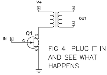
Well, it seems easy enough, we’ll just pop one of these self-biased little buggers in series with a transformer, as shown in Figure 4. The gain and input impedance of the transistor are such that we won’t even need more than this single stage – a lot easier than the three gain stages of your better tube amps and no fussing around with filament supplies, either.
The Problems
There are some reasons why the circuit of Figure 4 might not be appropriate.
First, as shown the JFET will draw a tremendous amount of current, and quickly take up smoking. We can fix that with some resistance on the Source to ground. Looking at the curves, maybe an ohm or so.
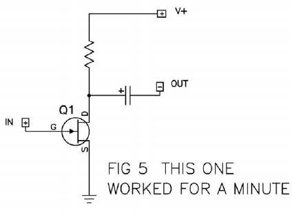
While we’re fixing things, perhaps we can do without the transformer at all. In tube circuits the transformer converts the high voltage / low current of the tube’s terrain to the relatively low voltage / high current of the speaker. Again looking at the JFET’s curves, we see that perhaps it isn’t necessary, and we can replace the transformer with a resistor and output capacitor, as in Figure 5. If you think that a capacitor is not an improvement over a transformer, then you’re welcome to your opinion, and in fact the transformer will raise the efficiency of the amplifier, but we are going to leave that for another time.
As we slowly crank up the supply voltage, we see that this certainly works, but the distortion is kind of high, and when we raise the voltage enough to get a good listen, we notice that the high end is a little deficient. After a few exciting seconds, the amplifier makes a popping noise, and then:
Nothing.
OK, we’re making progress anyway. Our problems (hereafter referred to as opportunities) are fairly simple. First, the transistor in question has limited dissipation. Even though it’s rated at 69 watts, realistically I’d be afraid to operate the package at more than about 10 watts or so. A TO-251 is a small device, and you have to work to get the heat away from it.
Second, the transistor is rated at only 24 volts. That just about enough to make a 2 watt amplifier with this circuit, and under these circumstances the transistor will be dissipating something approaching 16 watts. We might get away with this, but we still have pretty high distortion, and the top end is still down.
We can fix the top end – just get a preamp with a low output impedance. The 400 pF capacitance between the Gate and the Drain of the JFET is being amplified by the gain of the amplifier, and looks like more than 3200 pF. What? You say your preamp has a 10K output impedance? We can fix that.
Even with a low impedance preamp, the distortion is still high. Some opportunities just seem insurmountable.
The Solution
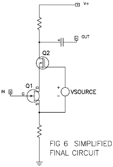
There is a single solution to these problems, called cascode operation. It is easy to cascode the Drain of the JFET with a partner device, as illustrated in figure 6. The partner device, operated Common Gate, contributes so little of its own character to the output that it doesn’t rate as a gain stage per se, but it shields the actual gain device from the output voltage. The gain variation due to fluctuations of Drain-Source voltage (the music) has nearly vanished, as has the need to charge and discharge the capacitance from Drain to Gate.
Even better, the Drain to Source voltage is not only nearly constant, but it is low, as low as we might want in order to keep the transistor reasonably cool. The power MOSFET doesn’t have anything to say about the output signal, but it has to take all the heat. Now we can crank this circuit up.
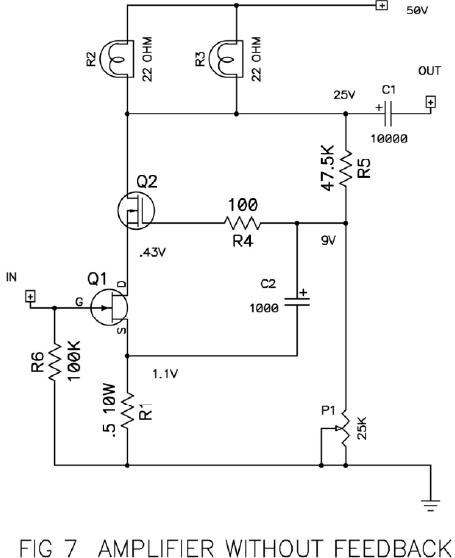
Figure 7 shows the Full Monty.
The current source resistor of the simplified circuit could be an ordinary power resistor, cooking along at 40 watts, or you can get a pair of 300 watt (120 volt) light bulbs, which are cheap and don’t need heat sinks. I like the clear ones because they look swell.
Just about all you want to know about this circuit is in the schematic, as I have posted the relevant voltages. There is wiggle room with regard to supply voltage and current, but you want to watch Q1 – its dissipation is the voltage across it and the current draw of the circuit, which as shown is about 3.2 volts and 2.2 amps, equaling 7 watts. The voltage and current are functions of the part itself, but we can adjust the voltage with P1. As we increase the value of P1, the voltage across the JFET increases, and the current will increase with it.
Construction of the amplifier is as straight-forward as any other amplifier. The power supply doesn’t require regulation, but it does require filtering to avoid supply noise from bleeding into the output. It is also very helpful if the supply comes up slowly on turn-on. You can obtain both these qualities with a capacitance multiplier as outlined in previous Zen articles. Q2 is mounted on a heat sink like any other power device, but we pay special attention to the mounting of Q1. I mounted mine directly on an anodized sink, using thermal grease and about a pound of pressure from a clip. I relied on the anodizing to insulate the case of Q1 from the heat sink. If you do the same, you will want to be certain that it is insulated, otherwise I recommend Mica and grease.
Of course you will want to put in audiophile-approved bypass capacitors in parallel with C1, but I leave you to choose the part.
Before you fire up the amplifier, check everything twice, (once in the evening, once in the morning) and set P1 to the minimum value. It should turn on drawing no current. Monitor the voltage the Drain and Source of the JFET and the Drain of Q2 to Ground. Slowly, very slowly, increase the value of P1. After a while, the Drain of Q2 should start to drop as the Drain and Source of Q1 start to rise. With a little luck, you’ll arrive at the voltages shown. The two light bulbs in parallel should measure about 11 ohms, so that the correct output voltage will give about 2.2 amps of current, and you’ll see about 1.1 volts at the Source of the JFET, where the current goes to ground through a .5 ohm power resistor.
The crucial test is to get the 25 volts at the output while maintaining a relatively low voltage across the JFET. We want to keep the dissipation on the JFET at less than 10 watts, and depending on the individual JFET, we should be able to manage that.
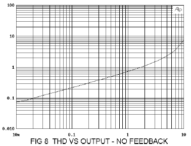
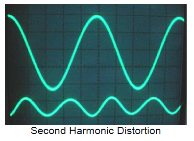
The distortion of the circuit versus output is shown in Figure 8. It rises with the classic second harmonic character, as shown in the following photo. Compared with a comparable MOSFET in the same circuit, it show about 1/3 the distortion.
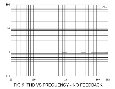
Figure 9 shows the distortion at 1 watt across the audio band. It is flat. It remains flat for source impedances up to several Kohms. The bandwidth with a 600 ohm source impedance is down a fraction of a dB at 100 KHz.
By virtue of the resistance of the light bulbs, the damping factor for Figure 7 is slightly less than 1. With an 8 ohm load, the gain is about 18 dB.
Naturally we look for any opportunity to improve the performance of this circuit, and if we don’t mind throwing away a little gain, we can consider using some negative feedback on the circuit.
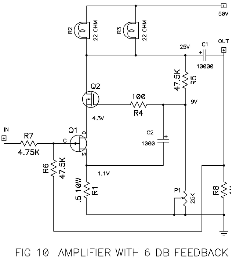
Figure 10 shows the circuit with feedback implemented. We have found a new connection for R6 and added R7 to form a feedback loop giving about 6 dB of feedback. The input impedance is now about 10 Kohm, and the damping factor is increased to 2. Due to the higher source impedance, the amplifier is down a bit more at 100 KHz, and the distortion climbs a little bit at 20 KHz, but nothing to get excited about.
In the circuit of Fig 7, a resistor to ground at the input insured that the Gate of the JFET was referenced to ground, and in this circuit R8 now provides that function, giving the Gate a ground reference when there is no DC source impedance.
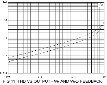
Figure 11 shows the distortion with and without feedback, and we see that the distortion is reduce by nearly half over most of the operating range. As we reach clipping, nothing can help us, not even feedback.
Conclusion
Well there we have it, an actual power JFET amplifier. There are many things that we will be able to do to make it better, and other designers will come along and add lots of parts and make it increasingly complex. In the meantime, you can get your feet wet with this simple circuit.
I’d like to spend some time talking about how great it sounds, but I would rather be listening to it, so I end here for the time being.
Copyright 2005 Nelson Pass
Acknowledgements: Figure 2 was adapted from the RCA Receiving Tube Manual, and Figure 3 was obtained from a Lovoltech data sheet.