Son of Zen
Nelson Pass
Introduction
The Zen has proven to be a popular and enduring do-it-yourself amplifier. The design addresses the audiophile's enthusiasm for singleended amplification, but is even more interesting for its exploration of the performance available at the extremes of simplicity, having only a single gain device. Judging by the mail, more than a thousand of them have been constructed, not including a couple of commercial rip-offs.
Incoming mail is an excellent barometer of interest and taste among the readers. Letters suggesting design improvements provide the direction and the excuse to proceed with the Son of Zen. It responds to the following common requests:
MORE/LESS POWER: Naturally I would expect an interest in more power, given the modest ten watts of the Zen amplifier. Surprisingly, I also experienced demand for less power, specifically five watts, from people fixated on that figure, and certain that ten watts was too much.
Son of Zen has been designed scalable, and can be built with an output from one to fifty watts without any change in the schematic of the amplifier itself. You need only change the power supply values and (possibly) the amount of heat sinking to achieve the desired output rating. Using a Variac in front of the power transformer, you can adjust the power rating with a knob.
DIRECT COUPLING: A lot of people are really concerned about capacitors, almost as many as worry about wire. Capacitor distortion is small compared to the sins committed by output transformers and the gain devices (tubes or semiconductor), but occupies a disproportionate share of audiophile angst.
The Zen amplifier cannot be direct coupled as designed, but the Son of Zen is completely free of capacitors in the amplifier circuit. Anyone concerned about capacitors in the power supply will be free to use batteries to power it.
NO FEEDBACK: The Zen depends on a modest amount of feedback for its performance. You don't like feedback? OK, it's gone.
HIGH INPUT IMPEDANCE: The Zen amplifier has a low input impedance, which helps lower distortion caused by the interaction of feedback network impedance with the input capacitance of the gain Mosfet. The Son of Zen can have any input resistor you care to use.
BALANCED INPUT: The Zen did not offer a balanced input. Son of Zen does, and achieves better performance with a balanced source.
EVEN SIMPLER CIRCUITRY: A number of readers expressed concern over the use of an active constant current source in the Zen, some going so far as to suggest that it constitutes a second gain stage. Well it doesn't, but just to make these guys happy, the Son of Zen is biased entirely by resistors, so that the only semiconductors are the actual gain
BUILDING THE CIRCUIT
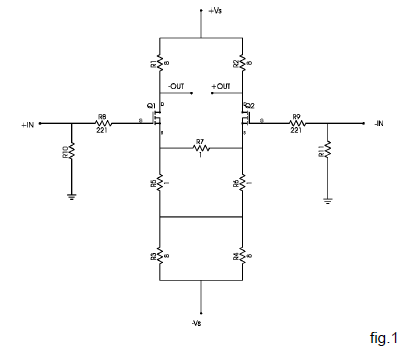
Figure 1 shows the amplifier circuit. Power Mosfets Q1 and Q2 are the gain devices. They are biased by eight ohm power resistors R1 through R4, and one ohm power resistors R5 through R7. Low wattage resistors R8 and R9 are there to prevent parasitic interactions between the Mosfets and the input cable/source, and low wattage resistors R10 and R11 provide an input ground reference and the nominal input impedance.
The circuit is supplied by two supply voltages +Vs and -Vs, and the loudspeaker is driven across the drain connections of the Mosfets.
The choice of power Mosfets for the gain devices is somewhat broader than those for the Zen amplifier. In general, any reasonably matched pair of power Mosfets will work, assuming that they meet the dissipation requirements of the circuit. I prefer to use the newer generation of Mosfets with higher transconductance figures and lower distortion than some of the early Mosfet parts. The actual Mosfets used in this project were IRFP240, simply because I have a good stock of them. It is also possible to use P channel Mosfets for the project, simply by reversing the polarity of the power supplies. I have tried it, and it works fine.
One of the problems enthusiasts had building the Zen amplifier was that the project was published just before the great Mosfet famine of 1995, and it was exceedingly difficult to get the parts. It will be easier this time around because Son of Zen is a little less fussy, Mosfets are more available, and I will be making matched pairs available for sale.
Digikey (1-800-344-4539) has IRFP240 and IRFP244 and similar devices available between $7 and $8 each.
The matching of the Mosfets helps achieve low DC offset voltage as seen by the loudspeaker and also helps to lower the distortion. If you want to match your own devices, you can simply place them in the working circuit, noting their Gate-to-Source DC potentials with a multimeter, and matching devices for the same DC voltage.
Figure 3 shows the dissipation in each of the eight ohm power resistors in the amplifier. You will note that at output ratings of 50 watts each of the four resistors will be dissipating in excess of 200 watts. For this project I used Dale NH-250 8 ohm 1% resistors, which are rated at 250 watts each. These resistors will require extensive heat sinking. Fortunately the thermal considerations for the power resistors are more lax than for the power transistors, and you can operate them closer to their ratings and at higher temperatures. I suggest that you place them on separate heat sinks from the transistors for this reason. Each of the resistors can also be made up of arrays of smaller resistors. You can, for example use a pair of 16 ohm resistors in parallel, or 4 ohm resistors
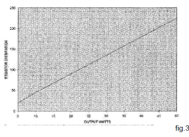
in series. The exact value of the resistors is not particularly critical, and variations from 7.5 ohms to 8.5 ohms will not make a significant difference, although the resistance values should be matched as much as possible. The Dale resistors I used are non-inductive, but this is not critical.
For the one ohm resistors, I used Dale NH-50 1 ohm .1%, which are rated at 50 watts. The one ohm resistors have the same sorts of requirements as the eight ohm resistors, except that their dissipation figures are only one-eighth the amount.
The input to ground resistors R10 and R11 can be any reasonable value. I used 10 Kohms, but you can easily go as high as 100 K ohms. R8 and R9 are nominally valued at 221 ohms, and could range from 100 to 470 ohms. R8 through R11 are low wattage types. Some of you will want to use Vishay or Holco resistors, while I settled for Vishay's subsidiary Dale's RN55D metal film types.
There is no PC board layout for this amplifier. All of the connections between the parts are by direct wiring. I trust that you will choose politically correct, audiophile approved wire.
BUILDING THE POWER SUPPLY
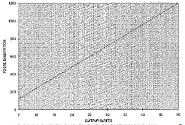
The Son of Zen requires a serious power supply. Figure 4 shows the total power supplied to the circuit versus the output power. For ten watts output, the power supply will have to deliver 200 watts. For fifty watts output, the supply will have to deliver 1200 watts. All the time.
devices themselves. There are no extraneous transistors, diodes, or what-have-you.
NO ADJUSTMENTS: There are no adjustments of any sort in the Son of Zen. You will not need any test equipment beyond a multimeter to confirm proper operation. The performance depends entirely on noncritical matching of gain Mosfets and resistors.
The whole thing sounds pretty ideal, doesn't it? There are two performance caveats to this design, both the result of filling the above audiophile wish list.
First, the damping factor is quite low, on a par with some of the tube amplifiers on the market. If you need an amplifier with a high damping factor, look elsewhere. You can improve the damping factor of the amplifier by scaling the resistor, but only at a heavy efficiency penalty.
Second, the efficiency of this amplifier is quite low, even by audiophile standards. Operation of a single channel at twenty watts will require about 500 watts worth of power supply and heat sinking. This would be a daunting consideration for a commercial amplifier offering, but does not represent an insurmountable barrier for the do-it-yourself enthusiast.
Nevertheless, this is a project requiring lots of heat sinking and big power transformers. There is a lot of latitude to this hardware, but be forewarned that this is a project for those who like their hardware big and their listening rooms warm.
CIRCUIT THEORY
The Son of Zen is what I will call a balanced single-ended design. In this case it refers to a differential pair of matched power Mosfets where a balanced signal is presented at the gates of the Mosfets and the speaker is driven across the drains of the Mosfets.
Is this a single gain stage? Yes, a differential pair is considered a single gain stage.
Is this single-ended? Each half of the circuit is clearly single-ended, although operating any pair of such circuits in balanced mode calls the concept into question, thus the term "balanced single-ended". As there are a number of amplifiers in the marketplace referring to themselves as single-ended, although clearly using balanced output stages, the oxymoron "balanced single-ended" provides a means of distinguishing this approach from the more "pure" single-ended designs.
In the case of this design, it is the balanced nature of the topology which allows the direct coupled operation not possible in the original Zen amplifier.
Alternatively, you can swap devices in and out until you get low DC offset at the output across the drains of the Mosfets. A procedure for matching Mosfets is also presented in the A75 amplifier project published in The Audio Amateur.
If you cannot manage to match your Mosfets, you can get some adjustment of the DC offset by placing resistors in parallel with R5 or R6. Start with trial values like 100 ohms.
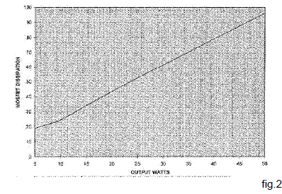
Figure 2 is a graph showing the dissipation in each of the power Mosfets versus the output power rating. Given a desired output wattage, you can see how hard each transistor will be working, and plan accordingly. The devices you use should have dissipation ratings considerably in excess of the dissipation point on this curve; I would suggest at least twice as much. This means that a Son of Zen with an output of 50 watts will need Mosfets rated at about 180 watts each.
Heat sinking for these Mosfets is very important to their reliability. The rule of thumb for heat sinking is that you should be able to touch the heat sink during operation. This requirement limits the temperature to about 55 degrees Centigrade, and assures a chip temperature within the device's ratings. You can run the devices at higher temperatures, but I would suggest having some spares, as it will reduce their operating life.
The Mosfets have electrically live cases, so mounting them on the heat sinks will involve the use of thermal grease and insulators. Mica insulators are the best. You can get insulators made of silicone rubber which do not need the grease, but they are not as good in my experience. The screws which secure the devices to the sinks must be tight without over-tightening. At Pass Labs we use torque wrenches set at 3.5 inch-pounds.
Mosfets are sensitive to static discharge, and should be handled carefully to avoid damaging the gate due to static. Elaborate precautions are not essential, just try to use some common sense when handling the devices. The Son of Zen is not provided with static input protection, and requires moderate care when hooking up the amplifier to a source. You can provide input protection if you want by placing backto- back zener diode pairs at each input to ground. The ratings of the diodes should be 10 to 16 volts.
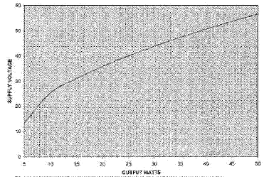
Figure 5 shows the supply voltage requirements versus output power. This voltage ranges from about plus and minus fifteen volts for a five watt output to plus and minus fifty-seven volts for a fifty watt output.
Figure 6 shows the suggested power supply schematic. The power transformer should have a VA rating about twice that of the dissipation figure obtained from figure 4, and have split secondary windings to achieve the plus and minus supply voltages. The nominal voltages of each secondary winding should be about twenty percent less than the DC voltage desired. For example, to get an output of 25 watts from the circuit, we will need a transformer with about a 1000 VA (one kilowatt) rating having split secondaries of about 32 volts each.
The power transformer shows twin primary windings, a configuration which allows operation in parallel for 120 volts AC or in series for 240 volts AC. This is a common feature in power transformers, but is not essential.
The rectifier bridge should have at least a twenty-five amp rating, and should have heat sinking to the metal chassis. The air core inductors L1 and L2 have nominal values of two milliHenries, and should be heavy gauge to carry as much as three amps DC. These are available from MCM as part numbers 50-375 (MCM 1-800-824-8324).
Capacitors C1 through C4 should be as high values as possible. High
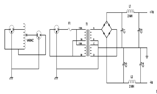
values can be achieved by paralleling capacitors if necessary. Lower impedances at high frequencies can be achieved by paralleling film capacitors with these computer-grade electrolytics.
Fuse F1 should be a slow-blow type rated at least twice the anticipated current draw. If the amplifier is projected to draw five hundred watts, then try a ten amp fuse. If it fails, try a larger one.
Figure 6 shows the use of a variable auto-former such as a Variac (tm) as an option prior to the power transformer. Plugging the primary of the power transformer into the output of a high power variable auto-former allows for a gentle startup, and also allows easy adjustment of the supply voltage. The particular variable autoformer I used was Superior Electric brand Powerstat type 3PN136B, rated at 0-140 volts AC and 22 amps.
Use of an Variac is not essential, but if you do not choose to use one, you should make an allowance for current inrush when the amplifier is turned on. The do-it-yourselfers I know are usually generous with the power supply capacitance, resulting in high turn-on currents from the AC line. Various means of suppressing these are available, including, but not limited to, power Thermistors from Keystone and available through Digikey such as KC003L-ND.
More ambitious constructors may consider the use of active regulation of the power supply. In this regard, there are no special requirements, except to make note of the high continuous currents they will be called upon to deliver. Active regulation will improve the noise measurements of the amplifier.
PERFORMANCE
Since there are no adjustments, turning the amplifier on for the first time consists simply of firing it up. Using a multimeter, confirm that the differential DC voltage across the speaker terminals is low, and that it is approximately one-third of the supply voltage above ground. The sources of the Mosfets should be about four volts below ground.
Assuming these conditions are fulfilled, the amplifier is very probably
third harmonic content. The amplifier is designed to be driven from a balanced source, but will operate with a single input, with less gain and higher distortion. Simply ground the unused input. Operating Son of Zen with a single-ended input will put some second harmonic content in the output, possibly what you will desire.
In this regard, the amplifier adapts itself to the characteristic of the source. You would expect symmetric distortion from a balanced source, and you might similarly expect even harmonic content from an unbalanced source (We aim to please).
The frequency response is flat from DC to several MegaHertz, depending on the source impedance and the inductance matching of the power resistors.
Assuming that the loudspeaker you are driving is efficient and forgiving of source impedance, the Son of Zen has a wonderful sound, very direct and clear, without the electronic veil imposed by complex feedback circuits. Modesty prevents further auto-review.
This project is being published simultaneously on the Pass Labs web site (www.passdiy.com ) and in Audio Electronics (formerly the Audio Amateur magazine). Check the web site for Mosfet availability. You can E-mail me at nelson@passlabs.com , or regular mail: Pass Labs, PO Box 219, Foresthill CA 95631.
operating properly. Sit with it for a while to insure that nothing gets too hot. You should be able to touch, if only briefly, the heat sinks carrying the Mosfets.
The amplifier will differentially reject power supply noise by about 26 dB, and so the output AC ripple should be about five percent of the supply. If you have too much output noise, you need more supply filtering. I easily achieved a 1 mV output noise using four 30,000 uF capacitors in the supply, and you should be able to match or better this figure.
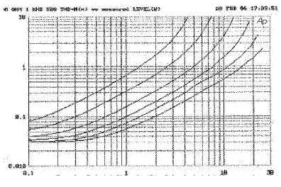
Figure 7 shows a family of distortion curves versus output power for several different supply levels, from about a 4 watt rating to 30 watt rating. These curves were taken at one kiloHertz, but I did not find significant variation versus frequency. The prototype amplifier went up to 30 watts with 45 volt supply rails, and drew about 700 watts per channel.
The distortion is monotonic in nature, characteristic of Class A operation, where distortion becomes vanishingly small as the output level is reduced. Operated with balanced input, the distortion is largely symmetric, reflecting the matching of the devices, and is dominated by