The Amazing FET Circlotron Construction, Continued
Michael Rothacher
Introduction
A lot of would-be audio projects die on the vine, even when printed circuit boards and components are readily available. The planning, layout, and construction of the chassis metalwork are sometimes the barrier. Perhaps, this is why complete kits are often the first choice of beginners. To get you building, I’m including some additional information, a few instructions, pictures, and a parts list. Wherever possible, I’ve tried to select suppliers who have online stores so you can just “click” your way to a complete kit of parts.
The Chassis
To simplify construction of the FET Circlotron we’re going to go retro-tube style, where the amplifier and all of its mechanical and electrical parts are attached to a plate that rests atop some sort of metal or wooden box.
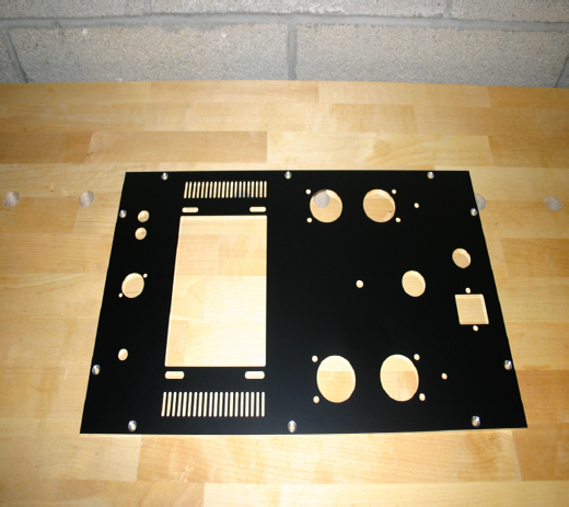
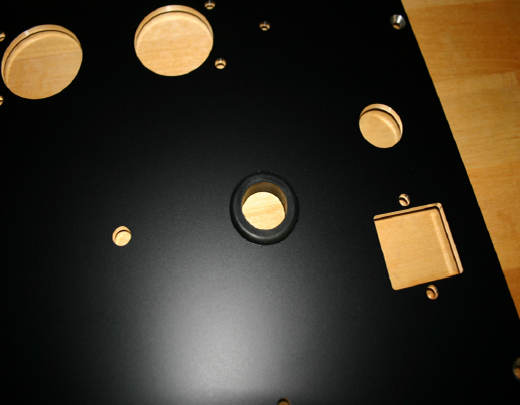
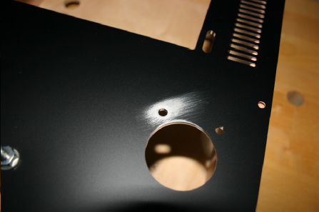
The top plate I used is pictured below. You can fabricate your own, or you can purchase a pair from www.frontpanelexpress.com. Front Panel Express offers custom machined panels you design yourself using their free CAD software. You can download my CAD file from the publisher’s site, and order them online. You can even order them in different anodized colors, add engraved lettering, or alter the layout for your own needs. This plate has holes for everything: heat sinks, power supply boards, transformer, rectifiers, IEC connector, power switch, XLR connector, and a bonus 3/8” hole for a future add-on to be disclosed later (we’ll just plug it for now).
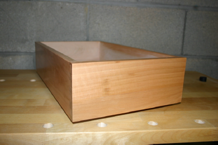
The box our top plate rests on measures 10” wide by 17” long by 4” tall. You can build your own from 1/2 inch to 5/8 inch lumber using simple joinery, or you can get fancy and try box-joints or even dovetails. The box also makes a handy platform for the top plate while you’re building.
NOTE: If you must have an all metal chassis, you might try the Hammond 17x10x3.
Now, I know I said you wouldn’t need a fully-equipped shop for this project, so if you’re not into woodworking, or you don’t have a friend who is, here’s a great cheat:
The beautiful dovetailed cherry box pictured below is actually a custom made drawer that you can order online from www.woodcraft.com., They ship flat so you’ll have to glue and assemble them. I finished mine off with a couple of coats of clear wipe-on poly followed by a coat of paste wax. You can paint or stain them any way you like. I can’t wait to see the first Lamborghini-green pair.
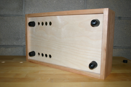
I recommend drilling some vent holes in the bottom right underneath the top plate vents. Also,drill some holes and attach feet to raise the boxes up a bit.
If you want your amps to really groove, don’t forget to install these “Space Age” badges.
They’re aluminum and black, and way cool. You can order them from Joe at www.amplates.com. He makes nameplates for guitar amps, and he cooked these up just for this project.
The Printed Circuit Boards
The PCBs are available from www.expresspcb.com. They offer free software for designing your own PCBs, then you upload your files to their website and they crank them out for you in a couple of days. You can download the files for this project from the publisher’s website. You’ll need to order four “Power” PCBs and two “Amplifier” PCBs. You can forego the silkscreen and soldermask and save some expense, if you prefer.
Making one-offs this way is really convenient, but not always the most economical approach. Perhaps some intrepid hobbyists will organize a group-buy to lower the cost of the set even further. The same could be said for the top plates. All I ask is that any sort of full-on commercial enterprise be avoided.
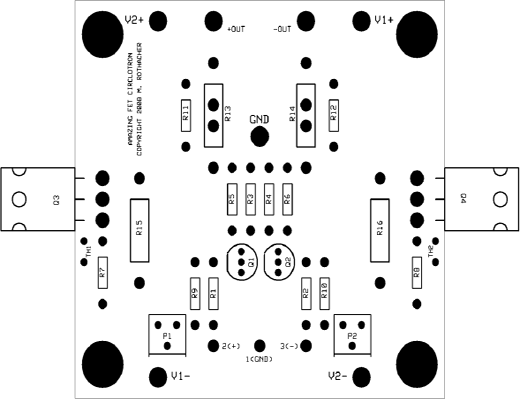
NOTE: The PCBs in the photos here vary slightly from the ones you’ll be using. The PCBs in the pictures were my prototypes, and after building the first pair I made a few changes. The changes are minor, i.e. larger holes for wires, and very slight changes in parts placement. I built four more channels with the final PCB’s and they performed as well or better than the prototypes.
The final version (the one you’ll be ordering) is shown here:
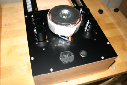
The Power Supply
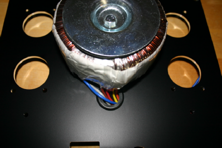
Install a rubber grommet in the 3/4” hole as shown below. Don’t skip this. The transformer leads will be fed down through this hole and the grommet will protect them from being cut.
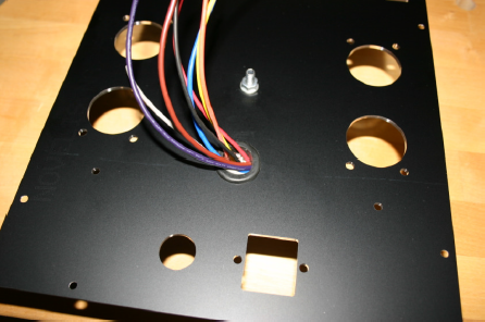
Now you can attach the transformer to the top of the panel and feed the leads through the grommet, out the bottom, as shown here. Securely bolt the transformer to the plate so it doesn’t vibrate too much when we energize it later.
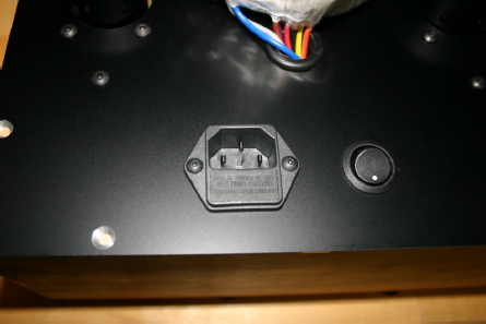
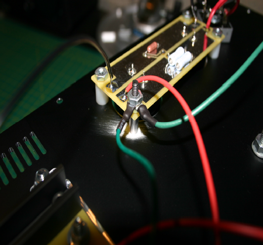
Attach the IEC connector and power switch. The power switch just snaps in. This is a good time to sand away the anodized coating around one of the power supply PCB holes as shown below. This is where you’ll attach your ground lug.
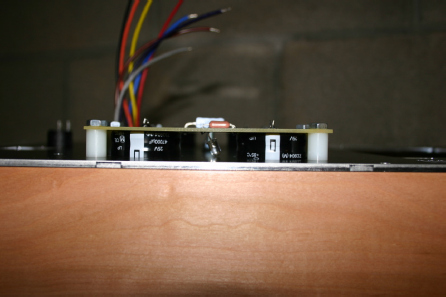
Assemble the power supply PCBs. The caps and LED are soldered to the top of the board, and the resistors are on the bottom. This assembly then gets flipped and attached to the plate so that the caps stick out the top. I used #8 hardware and 1/2” tall nylon spacers, except for the ground lug hole, where I used an aluminum spacer.
NOTE: the aluminum spacer in no way connects the power supply voltages to the chassis since the PCB’s mounting holes are isolated from the traces. I used the aluminum spacer so I could attach the ground lugs just under the mounting nut, rather than between the spacer and chassis. This way the boards sit level. This can be seen in the photo below. As mentioned in the main article, never connect any of the power supply terminals to the chassis. The supplies are floating in this design. Only the earth ground from your wall outlet and the signal ground from the amplifier PCBs will be attached to the chassis.
Now you can attach the rectifiers, and wire-up the mains connector, switch, and power supply boards.
This is a good time to test the power supplies. Install a slow-blow 1-2A fuse, attach a power cord and bring the line up slowly with a Variac, if you have one. Measure the voltage at the PCB output terminals with your multitester. You should see 25-26 Volts here since the power supply is currently only loaded by the LED and your meter. The LEDs should be lit.
If everything looks good, take a moment to dim the room lights and bask in the blue glow. Let out your best “Evil Genius” laugh – you’re half-way there.
The Amplifier
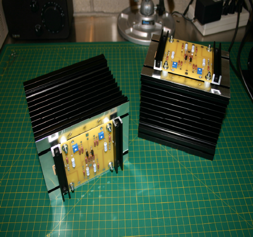
Assemble the amplifier PCBs and attach them to the heat sinks using 1/4” nylon spacers and M5 hardware. You don’t have to drill any holes for this. Just slide the whole assembly into the Tslots and make sure everything is centered-up. I recommend leaving the MOSFETs unsoldered at this point so you can adjust them to lie flat against the heat sink. Slide thermal pads squarely under the MOSFETs. You can also use mica insulators and grease. Now you can clamp down the MOSFETs. I used 3.8” pieces of aluminum channel with 1/4” drilled holes on 3.15” centers.Use M5 hardware here with compression or lock washers. You can get the channel at Lowe’s or Home Depot. I recommend using a drill press for the holes. A $70 10-inch bench model will work just fine and will come in handy for future projects.
NOTE: You can also drill and tap holes directly into the heat sinks, but the method shown here is pretty versatile, and applies nice even pressure to the transistor. You can apply a lot of pressure with this arrangement. Don’t overdo it. Snug+ will do the job. You shouldn’t need to crank on them. I used a cool little tool that looks like Doctor Who’s sonic screwdriver. It has a clutch that releases when a preset amount of torque is applied. I used 10 inch-lbs.
Once this is done, you can solder the MOSFET pins and bend the thermistors to make contact with the transistor mounting channels. You can even glue or clamp them in place if you like, just be careful not to short the leads.
Once the channels are complete you’ll need to attach them to the top plate with M5 hardware. Slide a hex head bolt into each T-slot on either side of the PCB then, lower the top plate over the heat sink assembly and align the bolts with the four mounting slots in the top plate. Center the heat sink and square it up with the top plate, then fasten with washers and M5 nuts as pictured below.
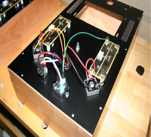
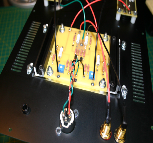
Install the XLR connector and binding posts.
NOTE: I used fully insulated binding posts from www.partsexpress.com. If you use the same posts, you have to cut away the little “key” on the insulators to fit them properly in the holes. Many kinds of posts will work here, and I had originally intended to use the more generic gold ones from www.vampirewire.com.
It’s time to wire everything up paying careful attention to the cross-connection of the + power terminals, which you can see in the photo above. Also, ensure a good ground connection. You can see the aluminum spacer, IEC ground lug, and the signal ground lug in the photo below. Tighten it all down firmly.
Once everything is wired, double-check all connections – then check them two more times.
Set-up and Adjustment
You’re ready to turn this thing on and adjust the bias according to the instructions in the main article. Take your time now. You’re almost there.
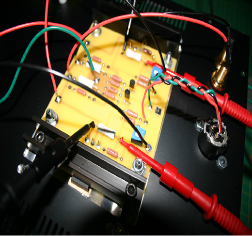
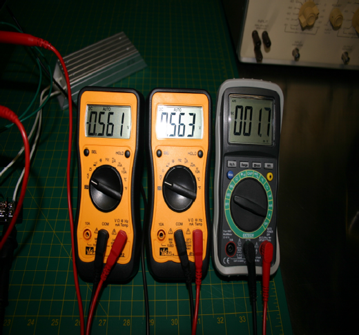
I used micro-clip adapters on my test leads to attach to the source resistors; otherwise you need six hands for this procedure.
Here we are using three meters to dial everything in. Set the bias, and set it again after a few hours warm-up with the chassis box on. Once the bias is set, and reset, you can permanently attach the whole top plate assembly to the box with wood screws.
That’s it. It’s time to take your amps into the listening room and try them out. Good luck. And most importantly – have fun!
PARTS LIST (ONE CHANNEL)
CHASSIS
REFERENCE
DESCRIPTION
SUPPLIER
SUPPLIER PART NO.
HEAT SINK, T-SLOTS, 0.32°C/W
NEWARK
10WX1015
TOP PLATE
FRONT PANEL EXPRESS
BOX 17" X 10" X 4"
WOODCRAFT
CONNECTOR XLR FEMALE
MOUSER
568-NC3FD-LX-B
BINDING POST INSULATED
PARTS EXPRESS
091-630
CONNECTOR IEC FUSED
MOUSER
16PJ522
SWITCH
MOUSER
612-RR3112ABLKBLKNAF
HOLE PLUG 3/8"
HOME DEPOT
T1
TRANSFORMER AVEL DUAL 18V SEC. 250VA
PARTS EXPRESS
122-620
BR1, BR2
BRIDGE RECTIFIER 35A 200V
VENTILATED CHASSIS COVER HAMMOND
PARTS EXPRESS
320-824
POWER SUPPLY (TWO PER CHANNEL)
REFERENCE
DESCRIPTION
SUPPLIER
SUPPLIER PART NO.
PRINTED CIRCUIRT BOARD
EXPRESS PCB
C1, C2
ELECTROLYTIC CAP 47,000 uF 25V PAN
DIGIKEY
P6901-ND
R1,R2
RESISTOR PANASONIC .47 OHM 3W
DIGIKEY
P0.47W-3BK-ND
R3
RESISTOR DALE ¼ WATT MF 1% 10K OHM
MOUSER
71-RN60D-F-10K
AMPLIFIER
REFERENCE
DESCRIPTION
SUPPLIER
SUPPLIER PART NO.
PRINTED CIRCUIT BOARD
EXPRESS PCB
P1, P2
POTENTIOMETER 3/8" SQ. 5K BOURNS
DIGIKEY
3386F-502LF-ND
Q1, Q2
P-CHANNEL JFET 2SJ74 BL TOSHIBA
Q3, Q4
MOSFET N-CHANNEL IRFP240PBF IRF
DIGIKEY
IRFP240PBF-ND
Or
MOSFET N-CHANNEL FQA19N20C FAIRCH
MOUSER
512-FQA19N20C
R1, R2
RESISTOR DALE ¼ WATT MF 1% 1K OHM
MOUSER
71-RN60D-F-1.0K
R3, R4
RESISTOR DALE ¼ WATT MF 1% 100K OHM
MOUSER
71-RN60D-F-100K
R5, R6
RESISTOR DALE ¼ WATT MF 1% 100 OHM
MOUSER
71-RN60D-F-100
R7, R8
RESISTOR DALE ¼ WATT MF 1% 2.2K OHM
MOUSER
71-RN60D-F-2.2K
R9, R10
RESISTOR DALE ¼ WATT MF 1% 49.9 OHM
MOUSER
71-RN60D-F-49.9
R11, R12
RESISTOR DALE ¼ WATT MF 1% 499 OHM
MOUSER
71-RN60D-F-499/R
R13, R14
RESISTOR PANASONIC .47 OHM 3W 5%
DIGIKEY
P0.47W-3BK-ND
R15, R16
RESISTOR PANASONIC 100 OHM 3W 5%
DIGIKEY
P100W-3BK-ND
Or
RESISTOR CADDOCK 100 OHM 30W 1%
DIGIKEY
MP930-100F-ND
TH1, TH2
THERMISTOR NTC 4.7K OHM
DIGIKEY
495-2161