Zen Variations 2
Nelson Pass
Introduction
Welcome back to the Zen Amp Variations. This is part 2 of many parts in which we explore some of the ways to make a very simple audio amplifier. In this and parts 3 and 4 we will embellish upon the original Zen amplifier circuit, improving the performance and creating the Penultimate Zen Amp.
You may recall that the Zen Amp is a single MOSFET transistor operated in what is known as Common Source mode in which the input signal is fed to the Gate pin, the Source pin is grounded, and we take the output signal off the Drain. In order to get this arrangement to work, we have to provide this transistor with a current source, which is just what its name implies. It is a source of current which provides the power for the gain device. In the case of the Zen amp, the current sources acts as a mediator between the positive voltage supply and the gain transistor, feeding the right amount of current into the circuit to provide the optimum conditions for the device.
The current source can be made as simple as a resistor (or a light bulb), but it is generally advantageous to make it out of something more complex, since using a resistor results in about 8% efficiency or so, and this being power circuit, wasting this much power gets costly and is socially incorrect. Just ask anyone who has built the Son of Zen, and they'll tell you that burning 600 watts to get 50 watts output is a bit over the edge.
In this article we will recap the operation of the original current source for the Zen, introduce an alternative current source, and then pull a trick out of the hat for a new source of current with a negative and occasionally imaginary source impedance.
The Original Source of Current
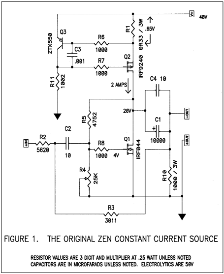
Figure 1 shows a version of the original Zen Amp. It is not exactly identical to the original circuit; I have played around with it to give continuity to this article's progress, but it is close enough.
The actual gain stage portion of the circuit is Q1 and the components attached to it on the lower half of the circuit. Q2 and the components in the upper half of the circuit make up the current source.
looking at about +40 volts, the MOSFET will begin conducting most enthusiastically.
To temper the enthusiasm of this conduction we install the remaining parts of the current source; R1, Q3, R6, C3, and R7. When current begins flowing through the MOSFET, voltage is developed across .33 ohm resistor R1 which will equal .33 volts for each amp of current flow. Q3, a PNP transistor, is set up so that it sees this voltage across R1. Bipolar transistors have a characteristic where they will begin to conduct when their Base to Emitter voltage approaches .66 volts or so, and when the voltage across R1 gets to about .66 volts, Q3 begins to conduct.
By comparison, MOSFETS begin conducting between 2 and 5 volts, and are quite variable between types and parts which is why we use a Bipolar device here. But I digress…
When Q3 begins to conduct, it limits the Gate voltage of Q2, and this forms a little feedback mechanism which limits the voltage across R1 at about .66 volts. R6, R7, and C3 are there to help make this arrangement stable and reliable, and we could possibly omit these, but we won't.
If the voltage across R1 is a stable and constant .66 volts, then the current through R1 is a stable and constant 2 amps, and that means the current through Q2 is a stable and constant 2 amps, and so we have a 2 amp stable and constant current source. For Drain voltages reasonably within the values of the power supply provided, the current will be fairly constant and good enough for this amplifier.
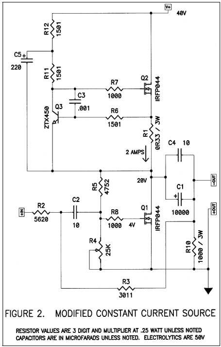
An Alternative Approach
There is more than one way to skin a current source, and Figure 2 shows an alternative circuit that performs the same function but with an N channel MOSFET instead of a P channel type. In this circuit, the corresponding parts retain the same reference numbers as Figure 1, with Q2 becoming an N channel part, Q3 becoming an NPN part, and R11 changing value from 10 K ohms to 1.5 K ohms.
The function of this circuit is identical to Figure 1 except that it has been turned upside down. The Gate of Q2 now has to go positive relative to the Source pin to achieve conduction, and so on. To keep the current through R11 fairly constant as it was with the previous version we have added R12 and C5 which "bootstrap" the AC voltage at the junction of R11 and R12 so that the AC voltage variation seen across R11 is low.
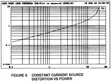
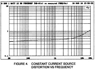
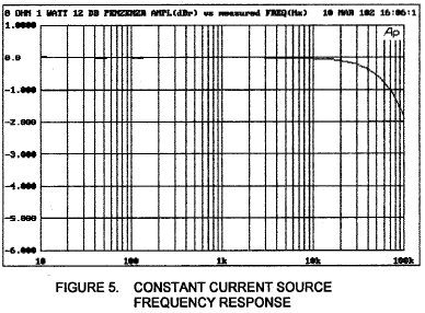
The performance of this circuit is virtually identical to that of Figure 1, and is documented in Figures 3 through 5. One advantage to the circuit of Figure 2 is that it uses the same device as the gain transistor, both being the cheaper and more easily obtained N channel types. The more crucial advantage to this innovation is that it can be further developed
this effect by minimizing the impedance of our feedback loop in the amplifier, Resistors R2 and R3. Unfortunately this also minimizes the input impedance of the amplifier, making it more difficult to drive. We will be addressing this problem in Part 4 and other parts of this series.
Figure 5 shows the frequency response curve of this amplifier, which is seen to be absolutely flat to 10 Hz and down 2 dB at 100 Khz. The damping factor of this amplifier is about 8 against 8 ohms, giving it a 1 ohm output impedance, typical of tube performance.
If you wish to improve your understanding of the lower portion of the circuit, I refer you to the original project articles, "The Zen Amplifier", Audio Amateur, issues 2/1994 and 3/1994. These can also be found on www.passdiy.com .
This type of current source is known as a constant current source. Ideally, a constant current source will deliver an exact, unwavering amount of current out of a connection (in this case the Drain of Q2) regardless of what is attached to the connection or what the voltage conditions at that node might be. If you leave this point unattached to some circuitry, an ideal constant current source will emit a small lightning bolt which will travel until it connects to something. The Zen Amp constant current source is not so ideal, but perhaps that is just as well.
The way this current source works is fairly simple. P type MOSFET Q2 will conduct current when its Gate pin becomes negatively charged relative to its Source pin. An easy way to make that happen is to use R11 to pull the Gate voltage toward ground, and with the Source pin
into a current variable current source as seen in the Pass Labs Aleph amplifiers.
Before we do that, let's make note of the performance of the circuit of Figure 2. Figure 3 shows the harmonic distortion curve versus output power into an 8 ohm load, and we see that this rises smoothly from about .1% at .1 watts, to about 2% at 10 watts. This is mostly second order harmonic distortion until you get above 10 watts, and by about 18 watts rms you are clipping the output with peaks at 36 watts. This is more power than we got out of previous editions of the Zen Amp by virtue of greater power supply voltage at 40 volts. Into 4 ohms, the amplifier clips at about 9 watts rms.
Figure 4 shows distortion vs frequency into the same 8 ohms at 1 watt levels, and we see an increase at high frequencies with a knee in the curve at about 6 KHz. The increase at high frequencies is due largely to nonlinearities in the input capacitance of power MOSFETs and is an unwelcome feature that we have to live with in this device. We minimize
The Aleph Current Source: the Altered Alternative
In 1991 I authored U.S. patent # 5,710,522 which detailed the operation of an active current source which was constant for DC characteristics but variable at AC frequencies and which could track an arbitrary percentage of output current to a load, relieving the active single-ended Class A gain device of some of the work. As a practical matter for audio, the best figure for that percentage is about 50%, and this allows for pure Class A operation to twice the current, boosting efficiency to an ideal limit of 50% over the 25% expected from a constant current source.
Instead of the infinite impedance represented by an ideal constant current source, this new variation has a negative impedance equal to twice the load impedance. If the load is 8 ohms, the current source will have a -16 ohm impedance, and the active portion of the amplifier will think it is driving 16 ohms. The reactive portion of the loudspeaker is similarly mirrored in the this manner so that it accurately creates a negative ghost of the load. Think of Sigourney Weaver with the mechanized loader in Aliens.
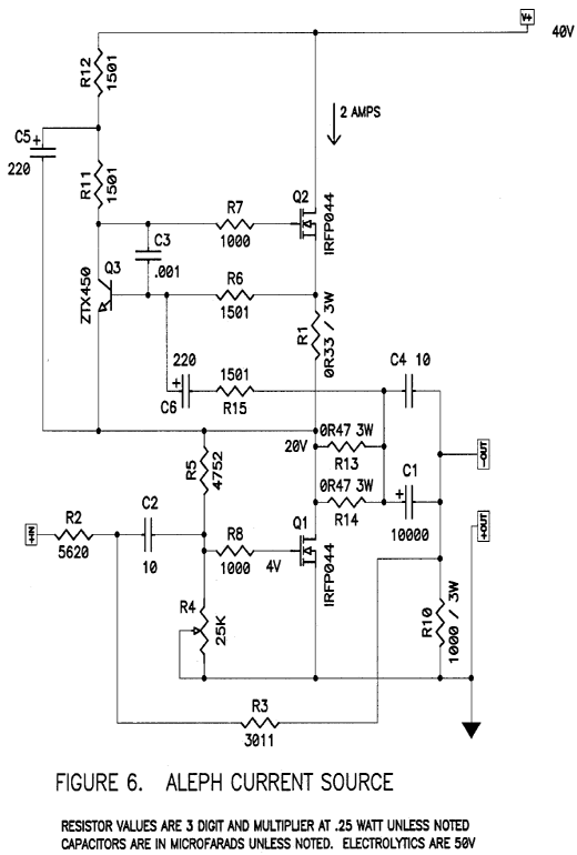
This circuit was implemented in the Pass Labs Aleph series of amplifiers and has become known as the Aleph current source. It is fairly painless to modify the current source of Figure 2 into this circuit, and the result is portrayed in Figure 6.
New components are introduced: R13 thru 15 and C6. R13 and 14 are two 3 watt .47 ohm metal film resistors paralleled to form a 6 watt .235 ohm resistor. They see the output current to the load, and sensing voltage appears across them which is proportional to this output current. R15 and C6 communicate this to the feedback junction at the Base of controlling transistor Q3, and the current through Q2 varies to support this output current.
The percentage of current contributed by Q2 is a function of the values of R13, 14, and 15 along with the other values of the current source, and in this circuit are set for best sounding performance, which is close to 50%. As a practical matter, we would adjust R15 to vary this value.
As with the other Zen projects, there is considerably leeway in the selection of values, and if you find that you wish to vary the values of R1, 13, and 14 for example, you will end up adjusting the value of R15 to get back to the 50% figure. Or maybe not; perhaps some other percentage will sound better to you.
In any case, to achieve this 50%, you would have to adjust R15 so that the AC current through R1 is one half the current going through the parallel R13 and 14. In the case of the values shown, that means that when the amplifier is driving a load, the AC voltage across R1 is 70% of the voltage across the combination of R13 and 14. You can use an AC voltmeter at 60 Hz to check this figure if you need to confirm proper operation of the circuit. Decreasing R15 increases the percentage, and vice versa. If you want a switchable variable/constant current source, install a switch to break the R15 circuit.
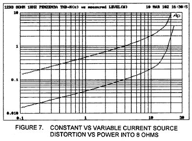
Figure 7 shows a comparison of the distortion vs power of the circuits of Figure 2 and Figure 6. It's a pretty straightforward result: the distortion drops by a factor of about 10.
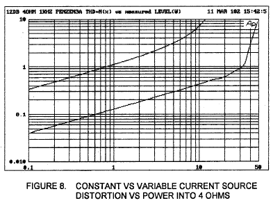
Figure 8 shows the same comparison at 4 ohms. Again, a factor of 10 reduction until about 9 watts, where the older circuit clips and the newer circuit goes on to hit 1% distortion at 35 watts.
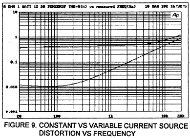
Figure 9 shows the distortion vs frequency for the two circuits. Alas, the dramatic improvement doesn't hold up as well at high frequencies, which we will be addressing in part 4.
The damping factor of the newer circuit is approximately 40, for an output impedance of about .2 ohms, five times better than the older circuit.
Outro
Well there you have it, the first major improvement of the original Zen Amp in 8 years. It sounds about as good as it looks. The bottom end is a lot tighter, there is greater clarity in the mid-band, and there is more power and dynamic range. You can operate this one balanced for about 70 watts into 8 ohms with even lower distortion. If you have already built the Zen, you can easily adapt it to the newer circuit, and it will perform well with the original 32 volt supply (although with somewhat less power).
In part 3 we will build an active power supply regulator for the Zen, and in part 4 we will raise the input impedance to 47 K ohms and clean up some of the high frequency distortion. The result is fairly spectacular with minimal additional complexity and cost. And finally, the Penultimate Zen will get a PC board and a partial kit will become commercially available thru www.passdiy.com .
The Aleph current source is still covered by U.S. patent # 5,710,522, but as a matter of policy we do not concern ourselves with DIY efforts. All others can send checks to:
nelson@passlabs.com