Zen Variations 7
Nelson Pass
Introduction
One of the performance issues raised by the original Son of Zen (Audio Electronics, #2, 1997) was its efficiency figure, which was charitably described as 4% (500 watts in, 20 watts out). You may recall that this was dictated by the original requirements - no feedback, no capacitors in the signal path, and a single gain stage.
Zen Variation 6 relaxed the requirements on feedback and capacitors in order to provide a tutorial exercise about “super-symmetric” feedback. The performance was improved in distortion and output impedance, but the efficiency was only slightly improved, largely because we used most of the original circuit.
In the first part of this piece, we are going to raise the efficiency from about less than 4% to nearly 6% simply by eliminating the negative power supply rail and biasing the differential gain pair with a constant current source. This will also give improved distortion performance with a single-ended signal source over the circuit of ZV6.
In the second part of this article, we will additionally raise the efficiency to over 16% by driving coupled inductors instead of resistors. This will about quadruple the efficiency of the original Son of Zen, but with much better performance in all areas except for the input impedance.
Of course, it is also a slightly more complex circuit, and will keep in mind that the Zen and its brethren are all explorations in achieving good amplifier performance as simply as possible. What constitutes “good” is observed from both an objective (measurement) and a subjective (listening) viewpoint. It is my personal opinion that the simpler the circuit, the more similarity there tends to be between these two, but not always.
Biasing With an Active Current Source
The transistors of the original Son of Zen were biased up from the negative supply and did not contribute to the available output of the amplifier in a direct way, so there was considerable waste of energy. They needed to see relatively high impedance in the biasing network and they also needed to run at the full output current, and so they ran near the full rail voltage and used up about half the power. An active current source can operate at quite low voltages (as low as 2 volts for a power Mosfet without significant degradation). At low voltage it can carry the full bias current of the amplifier, dissipate a much smaller amount of energy and still offer a much higher impedance than the original network.
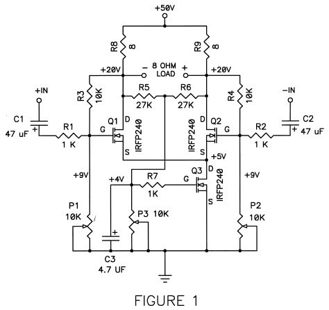
Figure 1 shows such an arrangement applied to a Son of Zen, along with the feedback networks R1-R4 and P1-P2 that we applied in ZV6. I am going to call it ZV7-R. Q3 is the current source, and it sinks about 7.5 amps of bias current split equally through Q1 and Q2, which are the gain transistors for this single-stage circuit. The Gate of Q3 is fed control voltage by a network of resistors R5, R6, R7 and P3. This network senses the DC output voltage on the drains of Q1 and Q2, and this is adjusted by the value of P3 so that the Drains of Q1 and Q2 are held at approximately 20 Volts DC. Since the outputs of these transistors have their signals out of phase, the junction of R5 and R6 sees just the common voltage, which is the DC figure.
If the DC value goes up, then the voltage on the Gate of Q3 goes positive, it conducts more current and the outputs of Q1 and Q2 go back down, and are thus held fairly constant. C3 is included for some filtering to avoid any audio AC signal or supply noise from making its presence known at the Gate of Q3. The circuit works quite well without it, but has a noticeably higher noise floor. R7 is the ever-present Gate resistor for Q3 which prevents parasitic oscillation. Most of the time we have used values of 221 ohms for R7, but in this case I found that some inductive loads could induce oscillation, This was cured by increasing the value of R7 to 1 Kohm.
As mentioned before, the voltage across Q3 can be as little as 2 volts, but the values of P1 and P2 have been set so that 5 volts appears across Q3. This is to allow margin for when the amplifier is driven by a single-ended input. In this case, one input is driven and the other is grounded and we see some voltage swing occur on the Gates of Q1 and Q2, and thus also on the Drain of Q3. By setting this voltage at 5 volts, variations as much as +/- 3 Volts can appear on the Drain of Q3 before the voltage across Q3 dips below 2 volts and distortion sets in.
If you are running the amplifier with balanced inputs, then this voltage can be set lower, as the variation at the drain of Q3 will only be a volt or so. In this case you can pick up slightly greater efficiency by running the Drain of Q3 at 3 volts or so by lowing the values of P1 and P2. Feel free to experiment, as these figures are not critical, and you probably won’t break anything.
P1 and P2 also help adjust the differential DC output. While this has been set at 20 volts by P1, you need to vary the differential DC value a bit to get low DC offset between the two outputs, as this is what the loudspeaker will see, not the 20 volts. These should be readjusted after amplifier warm-up and re-examined after the amplifier has broken in for a while. My standard for DC offset is 50 mV or less, and I have been known to put up with 100 mV.
The total draw of this particular circuit is 375 watts, and most of this appears across the 8 ohm resistors R8 and R9, which experience about 112 watts each. Q1 and Q2 will dissipate about 56 watts each, and Q1 will see about 37 watts. As with all the other Zen projects, and Class A amplifiers in general, adequate heat sinking is essential. The power resistors can take more heat, so it is often advantageous to give them separate heat sinks to operate at higher temperatures than the transistors, which we want to keep in the 60 deg C. range. This would be achieved by heat sinking with a thermal resistance of about 0.15 deg C. per watt.
Performance
The gain of the amplifier came in about 2 dB higher than ZV6 at 14 dB, and I did not adjust this out. It is reflected in the slightly lower damping factor (2.25) and slightly higher distortion numbers at the higher frequencies. Of course you can compensate this back down by increasing R1 and R2 to 1.25 Kohm, (or even more if you like).
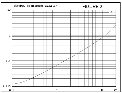
Figure 2 shows the distortion versus output power into 8 ohms for this circuit driven by a balanced source at 1 KHz. You will note that it bears strong resemblance to the results of ZV6, both being big improvements over the original Son of Zen.
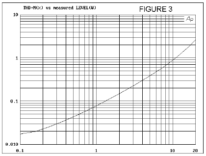
Figure 3 shows distortion versus output power with an unbalanced (single-ended) input where the other input has been grounded. Note that unlike Son of Zen or ZV6 there is virtually no degradation in this curve between balanced and single-ended inputs, and that the noise floor is quite a bit lower than the Son of Zen.
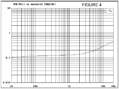
Figure 4 shows distortion versus frequency at 2 watts with a balanced input, where the distortion slowly climbs above about 3 KHz. As noted earlier in this series, this is due to the non-linear capacitance of the Mosfets, and is a little higher than ZV6, partly due to the higher gain figure. If you adjust the gain down, it comes out about the same.
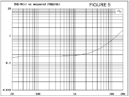
Unfortunately, this does not hold as true for a single-ended input, where the curves are no longer identical, and we see greater distortion than with the balanced case, about 3 times as much at 20 KHz. In and of itself, this is not a big deal, but it does point out one of the advantages of balanced drive, particularly in single-stage circuits, where they can use all the help they can get.
This is shown in Figure 5, where we find ourselves with roughly the same performance as ZV6 (again accounting for the gain increase).
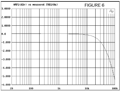
Figure 6 shows the frequency response, which is identical for both balanced and singleended inputs. It shows -.5 dB at 20 KHz and –3 DB at 60 KHz. This not as wide as the bandwidth of the Son of Zen, but there it is. If the ultimate in high frequency response is your goal and your source impedance is low, then the original may be better suited.
As with ZV6, the input impedance of the circuit is approximately 3 Kohm balanced, and 1.5 K ohm unbalanced, varying slightly depending on the Mosfets and the loading. Most preamp circuits will drive this, particularly the Bride of Son of Zen (Audio Electronics, #5, 1997), or you can easily apply the input buffer transistors found in Zen Variations 4 (Audio Express, December, 2002), which can get you up to 100 Kohm balanced.
Keep in mind that these projects are intended as tutorials (of a sort) and usually you should be able to apply ideas you see in one circuit to another. I calculated at least 128 variations of the single-stage concept, but I am only presenting the most interesting and educational. It is up to you to play mix-and-match with the ideas, or as they often said in my college textbooks, “This will be left as an exercise for the reader.”
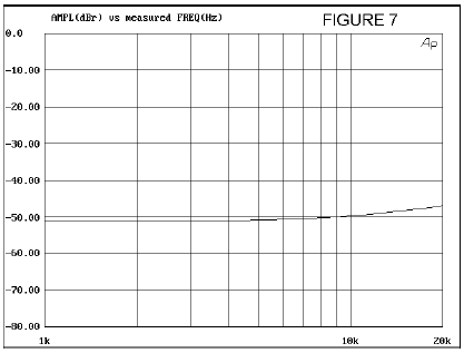
Figure 7 shows the input common mode rejection of the circuit, which is a pretty consistent –50 dB across the audio band. This is typical of all the Son of Zen type circuits (Not really much to say here, but I threw the graph in anyway).
Inductive Loading
One of the more intriguing possibilities for a Son of Zen with feedback is loading the outputs with inductance to the positive rail instead of those big 8 ohm resistors. Because inductors dissipate little energy and can provide much higher voltage swing, we expect them to dramatically increase the efficiency of this circuit, and so they do.
The original Zen and other non-balanced amplifying stages have some difficulty doing this because the high DC current which must pass through the inductor tends to saturate the magnetic cores found on high-value inductors. I have built a Zen with a 1 Henry coil (alright, a 1000 foot spool of MWS magnet wire) and it worked great. However with a balanced circuit like SOZ, if you use two inductors magnetically coupled (or one center-tapped inductor), the DC currents can be made to cancel magnetically, leaving only the AC component.
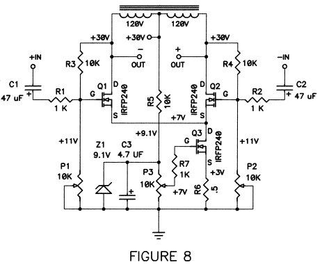
The obvious candidate here is a transformer with either two parallel primary windings or two parallel secondary windings, or one center-tapped secondary. I simply went out into my shop and snagged some samples of ordinary AC power transformers and plugged them into the circuit of Figure 8, which I am going to call ZV7-T.
Here we see basically the same circuit as Figure 1 with a pair of coupled coils replacing the pair of 8 ohm resistors. We note also that the bias circuit for Q3 has been altered so that it no longer looks at the DC output, which is going to be almost the value of the DC supply. If we track against this voltage we will find our bias wildly wandering with the value of the supply, and that would be double-plus ungood, as we used to say in 1984.
Instead, we use R5 to take current from the positive supply to bias up a 9.1 Volt Zener diode as a voltage reference. We place C3 across this to remove the remaining supply and Zener noise, and drive the Gate of Q3 adjusted by P3. To further stabilize this circuit, we place a nominal .5 ohm power resistor R6 in series with the Source of Q3. The bias current through the circuit is adjusted by P3, and you can measure this current by the voltage across R6. In the case of Figure 1, this has been set at 3 volts, which means that the circuit is drawing 6 amps total at a supply voltage of +30 volts, which is 180 watts. By the way, this .5 ohm resistor will be dissipating about 20 watts. I suggest a 50 watt resistor mounted on the heat sink.
Why the lower supply voltage? Because the coupled inductors can swing much higher voltage than the supply – in an idealized case, they would peak at twice the supply.
I tried a number of transformer primaries and secondaries, and quickly found that the low voltage secondary windings didn’t give me as much inductance as I needed, and so I concentrated on using the primary windings as my load, which worked much better. I left the secondary windings open. The example of Figure 1 and the curves which follow, Figures 9 through 14, were taken with a 300 VA Plitron toroidal transformer. I also took some data with a similar, but much larger transformer. This examples uses an off-the-shelf AC line power transformer, not at all optimized for audio work. Of course you could always go out and buy transformers actually designed for audio use, but how many of you have some nice piece of junk that you can use for free? What is surprising here is how well it works. Just shows that trying something out for the hell of it can have a good outcome.
When you are driving transformers in a balanced configuration like this, it is critical that you find the center operating point of the magnetic core in order to get the lowest distortion. This is more critical with toroidal type transformers as they have tighter magnetic coupling. “EI” type transformers are not as fussy, corresponding to a less efficient magnetic circuit. Either type of transformer will work, and either type still needs to be adjusted for lowest distortion.
Unfortunately, finding this point is a little trickier that you might think. I started out by simply adjusting P1 and P2, seeing to it that the DC potential across the windings was exactly the same on the premise that this would be the magnetic center. Not so. Then I went to great care to insure that the currents were exactly equal, regardless of voltage. That didn’t quite to it either.
Finally I adjusted the balance for the lowest distortion, and then I came back and adjusted it again later after the circuit had warmed up. It worked a lot better this way. What does this mean to you? It means that I hope you have a distortion analyzer of some sort. It doesn’t have to be a very good analyzer, but I don’t recommend adjusting the circuit without one. If you can’t buy a cheap used one, then build something. Try the IM analyzer recently featured in Audio Express, or build a notch filter. Anything.
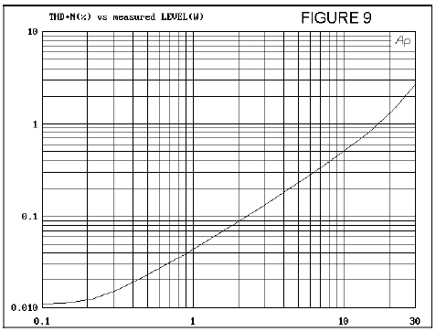
Figure 8 shows the circuit voltages that worked out best for me, and Figure 9 shows the resulting distortion curve to 30 watts into 8 ohms with a balanced input at 1 KHz.
For a 60 Hz AC power transformer not designed for audio, this was not shabby at all, and curious to see where it would fall apart, I pressed on with the same series of bench tests.
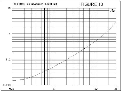
Figure 10 shows the same test, conducted with a single-ended input. As before, the results are nearly identical, except for slightly less noise and distortion with a balanced input.
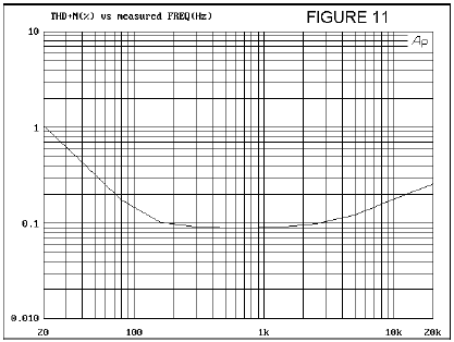
Figure 11 shows the distortion versus frequency at 2 watt output with a balanced input. Here we start seeing some of the weakness of the transformer approach, with some core saturation beginning to occur at the lower frequencies. This sort of curve is typical of a lot of tube amplifiers – one could almost imagine this amplifier having that sort of sound.
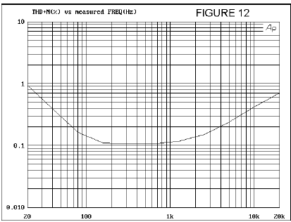
Figure 12 shows the same test with a single-ended input. In both cases we note the increase in distortion expected at higher frequencies, but we see a new component at lower frequencies, reflecting the lower impedance of the coil and the distortion of the magnetic core.
The distortion increase at the bottom end is a real concern, given that figure 12 is taken at only 2 watts output, and the distortion will dramatically increase with level. This is not the sort of transformer we would expect to deliver a dynamic bottom end with a lot of woofer control, but at the same time, we don’t expect that of any Zen or Son of Zen type circuit (at least not so far) and we usually find ourselves using these amplifiers where the mid and high frequency characteristics are the most interesting. While I followed through with the two remaining tests, my eye was already straying toward a really big transformer, one that would surely give better bottom end.
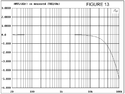
Figure 13 shows the frequency response of the circuit, which was the same for both balanced and single-ended inputs, and we see that it is about 3 dB down at 70 KHz. In this regard it is not much different from the resistively loaded circuit. Clearly the magnetic core characteristics and winding capacitances of our AC line transformer are not creating problems at the higher frequencies.
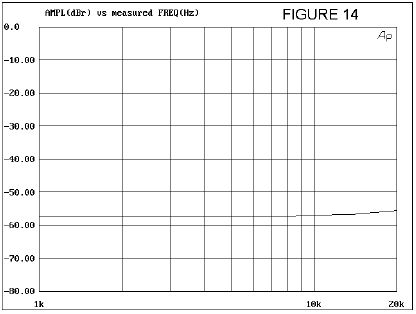
Figure 14 shows the almost boringly superlative input common mode rejection:
So much for that. Right away I plugged in a big heavy 1500 VA toroidal transformer instead of the 300 VA documented above. The low frequency distortion vanished by comparison, and for some unexpected reason the high frequency distortion was also reduced (and I don’t know why).
The other tests came out about the same, and I did not see a significant loss of high frequency response that I might have expected. The distortion figures immediately point toward the use of bigger transformers. No doubt your results may vary depending on what you try. Oh yeah, and the damping factor was a little lower at 2.25
The biggest thing to be said is that the efficiency of the circuit climbed above 16%, at least a four-fold improvement, giving 30 watts output for a 180 watt input.
Listening tests
I listened to the amplifiers of Figure 1 and Figure 8 with a Wadia 16 driving the balanced inputs of the amplifiers into a pair of Seas W17EX-002 5.5 inch magnesium cone woofers with Vifa D25TG 1 inch polymer tweeters mounted in 6 foot transmission lines and single-pole crossovers. I listen to a lot of stuff, but because of the relative inefficiency of the speaker and low power of the amplifier I mostly stayed with fairly simple solos: vocal, saxophone, piano, violin. I like to hear these amps at their best, and big orchestral passages are not their strong point.
Basically, I found little to distinguish ZV7-R (Fig 1) from ZV6. If you’ve already made a Son of Zen and given it the ZV6 feedback loop, then there’s no reason to bother. If you are considering ZV6, then I recommend ZV7-R as it is a little simpler on the power supply and has greater efficiency. I also recommend it over ZV6 if you are using a single-ended input connection, as the performance is significantly improved, although I did not perform listening tests with just the single-ended input.
ZV7-T was a different story. I listened to the circuit of Figure 8, and in spite of some of its measured shortcomings on the bottom end compared to ZV7-R, I found it more lively and musical. This is not to say that it was more accurate – it was simply more interesting and enjoyable for the time I have spent with it (which hasn’t been very long).
Walking on the Wild Side
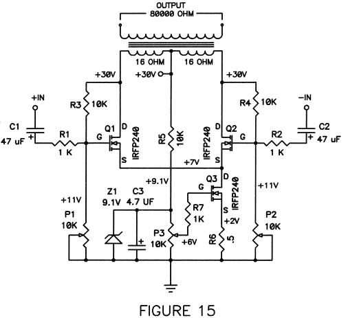
I didn’t just try AC power transformers. One of the samples that I hauled out of storage (think of the warehouse in Indiana Jones and the Lost Ark) was a Hammond 106940, the transformer that powered the legendary Dayton-Wright electrostatic loudspeakers immersed in Sulfur Hexaflouride. These monster transformers weigh about 50 lbs and feature four 8 ohm primaries and a single 80,000 ohm secondary, for a 100:1 step up (unless you drive all four primaries in parallel, for a 200:1 step up – scary thought).
Well who could resist, I ask you. The result is Figure 15, configured for a 50:1 step up and running the primaries in series for 16 + 16 ohms.
The configuration is the same as ZV7-T, except that the output is taken off the secondary of the transformer for the purpose of driving the stators of an electrostatic loudspeaker. I am calling it ZV7-E. Unfortunately I did not have an appropriate set of panels around, and I was unable to listen to this or even load it properly, but I did take the following set of curves from it.
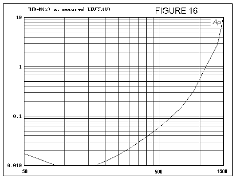
Figure 16 shows the distortion versus output voltage at 1 Khz:
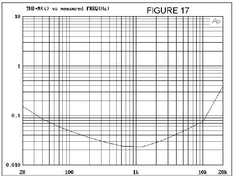
Figure 17 shows the distortion versus frequency at 100 volts output:
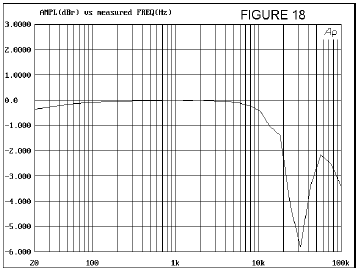
Figure 18 shows the frequency response unloaded:
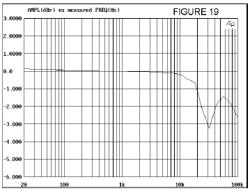
Figure 19 shows the frequency response with some resistive damping applied to the primary windings:
As I said, it was unfortunate that I was unable to get a listen, but I have applied modest amounts of feedback around these transformers before, and had good results. The 30 Khz resonance seen in the above curves dropped down by a factor of 2 when they were originally loaded with the Dayton Wright panels, so you can imagine the curve shifting left about half an octave or more with the 50:1 step up and loaded with a typical electrostatic panel.
We’ll just have to save that for another time…
Copyright 2004 Pass Laboratories
SuperSymmetry is a trademark of Pass Laboratories