
After you acquire the devices, you will need to test them. You might consider running lots of tests on these transistors, but only one is essential: measuring gate-source voltage versus current. The greatest variations occur here, and it is necessary to do some matching to get proper performance. This test will also tell you whether or not the device is broken. The test is simple and requires a power supply, a resistor, and a DC voltmeter. Figure 12 shows the test hookup for N- and P-channel types. The supply source resistance (R1) is nominal, and is found from I =… More...
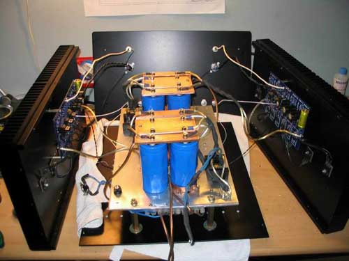
Here are some great project-submissions folks wanted to show-off. They don't directly correspond with a single PassDIY project, but we still fealt like they should have a home. Great work everyone! More...
Copyright © 2016 Pass Laboratories, Inc. All rights reserved
Telephone: 530.878.5350