Balanced Zen Line Stage
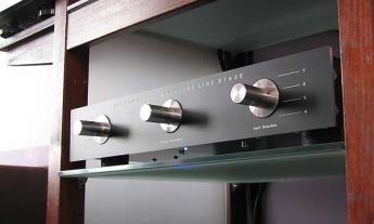
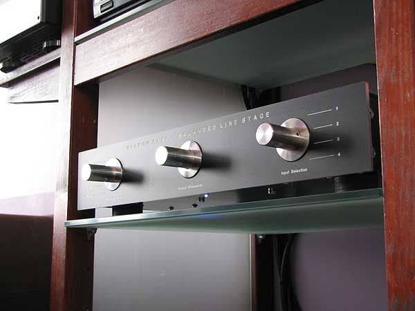
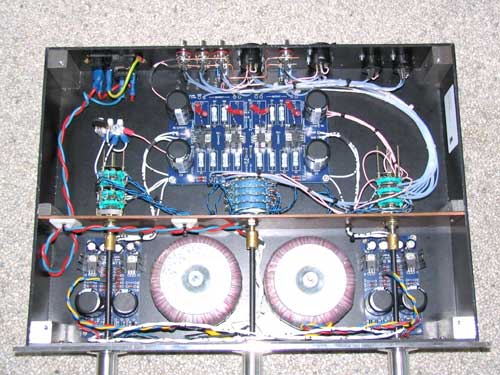
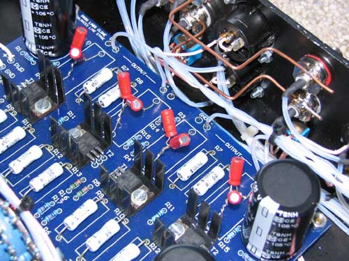
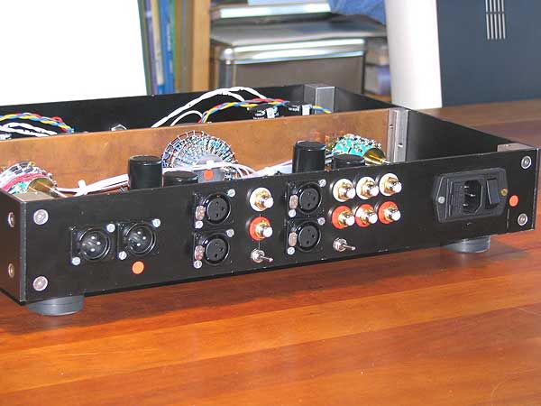
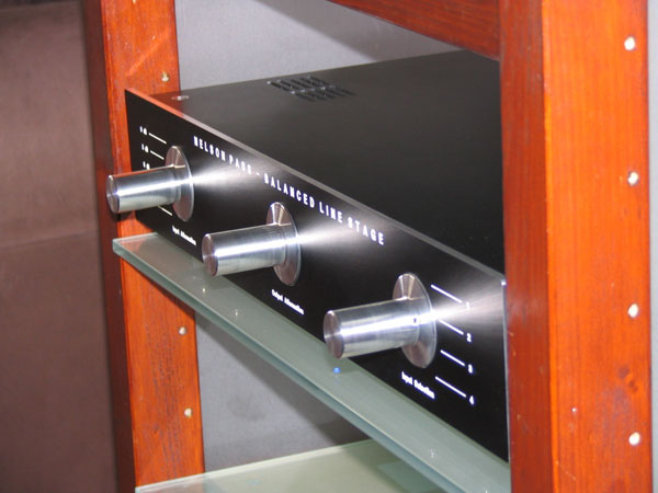
Recently, I have finished my X-Rated Balanced Line Stage (X-BLS). First some non-fascinating basics of the building process: the amp is mostly made of the parts recommended by Nelson Pass in his BoSoZ-paper. I sticked to the passive current sources on the tails of the differential pairs. As output capacitors I used pairs of 4,7 uF Black Gate type N electrolytes in the Super-E configuration. In the power supply, besides the big Panasonic 1000 uF caps, I used four Black Gate Standard 10 uF capacitors and two 2 * 30 V 80 VA transformers by Amplimo. The IRF610s were matched and the printed circuit boards I obtained from Kristian Kljucaric. Each channel has its own power supply board. I used Cardas RCAs and Neutrik XLRs. The internal signal wiring was done by Teflon insulated solid-core silver wire. Power supply and ground wiring was done with "F16 fighter plane approved" Teflon insulated silver plated copper wire. As this was rather stiff, I used CAT-5 wires to connect the stepped attenuators I used between the PCB and ground. I constructed a star signal ground which is connected to chassis ground by means of an NTC. The chassis is made from 3 mm black anodized and laser cut aluminium. The switches were placed on a 3 mm copper plate to shield the power supply section from the pre-amp circuit, as can be seen on the pictures. The 4 mm front panel was made by Schaeffer/Front Panel Express. The three knobs were turned from solid aluminium. The one thing that needs to be done to them is to polish them some more and to get them anodized. The mandatory blue led was fitted to the bottom of the pre-amp instead of the front panel because I did not want to disturb the symmetrical lay-out of the latter. This gives a nice bluish effect to the glass-shelf underneath the X-BLS.
In the following I would like to describe three of the construction problems I have dealt with, each of which not significantly discussed at the diyAudio.com Pass Labs forum. These problems are: (1) volume and gain adjustment of the X-BLS, (2) the "Pin 1 Problem" of balanced inputs and outputs and (3) ground switching of unbalanced inputs.
Volume and Gain Adjustment
The main problem I confronted myself with in constructing the X-BLS was the volume control. As you probably know, there are several options to choose from, e.g.: (1) at the input by attenuating each phase of the signal, (2) at the input by attenuating the signal between both phases, (3) at the output by attenuating each phase of the signal, (4) at the output by attenuating the signal between both phases and, finally, (5) by varying the gain of the differential pair by adjusting the amount of resistance between the sources of the MOSFETs. To make things evens more complicated, when you do not want to use ordinary potentiometers, you have to choose the type of attenuator: series, ladder or shunt. Each of these attenuator-types can be materialized either by hand controlled switches or micro controlled relays.
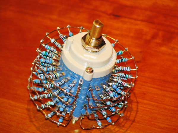
The amount of options available to choose from can almost drive you nuts. So I decided to solve this self-constructed problem by building several prototypes and to let my ears decide upon the right solution. I decided to keep it relatively simple and choose not to use relays. The one thing that remained the same during my investigations was the 2K2 shunt attenuator at the output, which I designed to offer 48 dB attenuation. When Aleph power amps are used, 48 dB attenuation is enough but when higher gain power amps are used I would advise you to use an attenuator of at least 60 dB. The necessary 23-position switch I obtained from Steinmusic (http://www.steinmusic.de) in Germany. It lowered my funds by some 50 € and makes absolutely no switching noise. A true bargain, if you ask me.
Prototype 1
Instead of the fixed 39K feedback resistor, I used a five position switch (NSF rotary silver-plated wafer switch from RS-Components) to vary the amount of gain between 2 dB and 10 dB. To calculate the right resistor values I used the free Simetrix simulation tool. Sound wise I discovered that lower gain (more feedback) led to degradation in sound quality. The effect was rather subtle but audible still. On with the search...
Prototype 2
I put back the 39K resistor in the feedback loop and placed a switch between the gates of the IRF610s (after, not before the 220 Ohm resistor) to attenuate the input signal between 0 and 24 dB. Again, Simetrix was used to calculate the resistor-values. This particular solution worked quite beautifully, however with one negative side-effect: when the shunt-attenuator was turned up all the way (i.e. 0 dB attenuation) there was a hiss audible, which was absent when the gates of the MOSFETs were not connected. Because of this hiss, I decided to do some more experimentation to reach audio nirvana...
Prototype 3
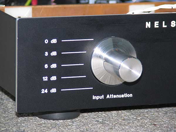
I removed the attenuation between the gates of the MOSFETs and put a 1K shunt-attenuator at the input instead. A ladder-type would have been "better", because of the non-varying input impedance, but was expensive to make. As I made this input-attenuator as a fit-and-forget device to optimize the input level dependent on the loudness of my sources, I did not consider the varying input impedance a problem too big. Sound wise, attenuation at both the input and the output turned out to be the right alternative to obtain sonic bliss in my particular set-up.
Ironically, I could have saved me a lot of time when I had "listened" to Nelson Pass in the first place. After all, he recommends adjusting the volume at both the input and the output. My time consuming experiments were fun though and I have learned a great deal. My experiments indicate that adjusting the amount of feedback to control the gain of the X-BLS is not the way to go. As to why this is so, I have no explanations to offer.
Wiring Balanced Input and Output Connections
Another construction problem I created, relates to the right way to realize the balanced input and output connections of the X-BLS. While I was studying some specifics of balanced operation, I read some Rane-notes (http://www.rane.com) about the "Pin 1 Problem" of making balanced connections between equipment. In the BoSoZ-paper, Nelson recommends to connect the signal ground to pin number 1. According to the folks at Rane, this is common, however bad practice. They recommend to attach pin 1 to chassis ground and to keep the signal grounds between balanced components separated. I decided to give the Rane-solution a try, only to find out that Nelson's solution is quite elegant when it comes to connecting both single-ended and balanced components to the line stage. I had to use toggle-switches and a rather complex wired source-selection switch to realize inputs that can be used both single-ended and balanced in the Rane approved way. At the output of the pre-amp, pin 1 is also tied to chassis ground. In this way, there is a true galvanic separation between my X-BLS and my Aleph 5 monoblocks. The amps are deadly quiet, no hum whatsoever can be heard trough my speakers. Be careful however because the Rane-solution may not work in all set-ups, at least to some very knowledgeable folks at diyAudio.com, which is probably the reason why Nelson recommends to tie signal ground to pin 1 at both the input and output of the balanced line stage. Whether or not the solution I opted for is better from a sonic point of view, I do not know but theoretically it is the more satisfying one, which of course says absolutely nothing in audio. Therefore, I can not offer definitive recommendations regarding the "Pin 1 Problem".
Ground Wiring of Unbalanced Inputs
The third construction problem I created concerned the grounding of the RCAs. Because I opted for a stepped switch with one wafer specifically used for signal ground, I thought it would be interesting to not only switch the signal but also the ground of each input. It worked but gave some switching noise. Therefore, I decided to connect the grounds the RCAs of each channel by means of a solid copper wire that was directly tied to the star ground (common practice). The switching noise was gone and the pre-amp remained as silent as before. Apparently, switching the input-grounds has little effect, at least in my set-up.
As to the sound ...
I hope my research investigations are of interest to some of you. It was fun to construct the X-BLS and it is even more fun to listen to. The sound of the pre-amp is wonderful, or lack of sound for that matter because it is barely noticeable when compared to my previous pre-amplifier. The "unique selling point" of this design is its lack of compression which makes it truly musical and definitely not "HiFi-ish", at least IMHO. In addition, it is very smooth, detailed and spacious. I am very happy to have built this particular design and urge you to do the same thing if you enjoy listening to music for hours without a break. The X-BLS is very gentle to the ears. Make that to your wallet also considering the high sonic quality and low building costs involved. Thanks Nelson for being so generous to the DIY-community and the participants at diyAudio.com for sharing their expertise.
Jan-Peter Vos
The Netherlands