Balanced Zen Line Stage
My Balanced Zen LS DIY journal
Why BZLS
I am always wanted to make my audio and love music since Junior High. After 30 years, I finally wanted to make one for myself. My friend had told me the designs about Nelson Pass and his famous products. After some study, I decided to pick this Balanced Zen Line Stage as my first project to try it out! My major is not EE and therefore, I have to run to local library to refresh myself with all the Electrical and Electronics knowledge that I left in my college life! From Nelson Pass' suggestion, I picked this BZLS to try out, so that I can have more confidence to reach my goal of making an Aleph 5 and an Aleph-P 1.7. As it turned out, it really is a wonderful project to start with! I really enjoy it, particularly is its sound!
The Parts List
I compiled my won parts list from Nelson's article. I checked all the available parts number and pricing from both Digi-Key and Mouser and purchase the best price and quality I can get with my budget. Some of my parts came from eBay and I found their quality isn't that bad, as long as you know what you are buying! In addition to the source above, I also purchased the parts from:
http://www.partsexpress.com -- RCA female jack and OFC wire
http://www.hndme.com -- nichicon capacitors and shrink tube, silver-plated hook up wire
Local Radio Shack -- any immediate supply, such as silver soldering.
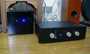
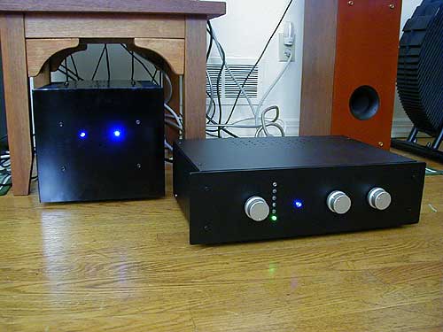
The Case
I purchased the case from Taiwan (http://www.diysong.com). It is meant for general amp use. The price, including surface shipping, is about $70 USD. The case came only with AC IEC outlet hole and fuse hole. I have to drill the holes for XLR, RCA, enlarge the fuse and power switch hole. The good thing is that Aluminum is not that hard to make holes on it. The challenge one is the XLR holes. My suggestion is to use a Drill press, if possible! If you are drilling the XLR hole manually, then buy the big hole drill a little bit smaller, as it will move around when you drill it. In my case, I bought one drill of 22 mm for the 24 mm XLR in the spec. The figure on the left is the drill I used for drilling the XLR hole.
Matching the MOSFETs
All MOSFET IRF610 (Q1 & Q2) are matched to 0.01V. The Q101 and Q102 does not need to be matched, but they tend to run very hot! Be sure to add additional heat sink to it! For matching the device, you can refer to here. The resistor I used is 2.2K. 500 Ohms is also fine. When matching, make sure to test it until the digits stabilized! I tested each one for about 20 minutes each, but I noticed that 10 minutes is good enough!
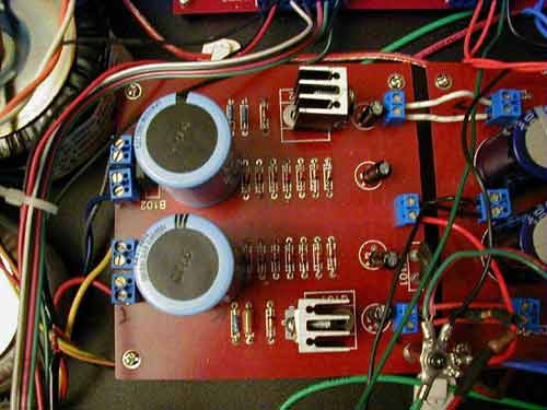
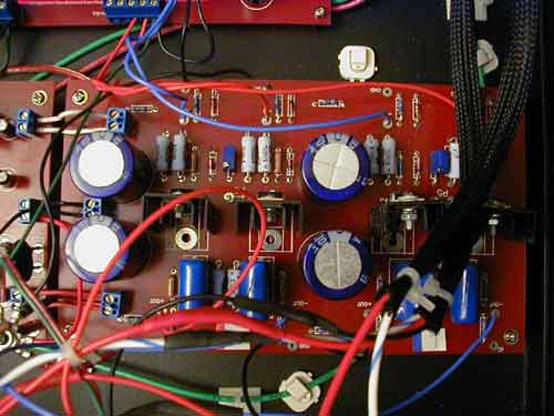
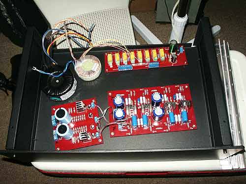
Power Supply Section
I used one Plitron 120VA/2x60V, instead of 2-30V transformer in NP's article. If you order it, be sure to order the mounting kit also, because it is not included in the price! The quality of this toroidal transformer is very good! I also use an additional 12V toroidal transformer to drive the Input Select board. This 12V transformer is a ready-made by Avel Lindberg from partsexpress.com The Plitron transformer has epoxy sealed in the middle, whereas the Avel does not! I added my own epoxy to the Avel transformer (and drill a hole in the center later). I hope this will reduce the vibration from the trans! I also increased the PSU capacitors to 1500uf/160V, and bypassed with two 0.47uF/220V Polypropylene capacitors. As I mentioned above, the Q101 & Q102 tend to run very, very hot! I set the mosfet upright and add the heavy duty heat sink to make it cooler! I buy these from Radio Shack as they work better than I parts used in the article (from Digi-key). The case I used has plentiful space to hold the BZLS. The power line is protected by the Thermistor built-in on the PSU already; therefore, there is no need to add one in the transformer AC primary side; although, adding one more on the primary AC is not going to hurt, either! Make sure to ground the Thermistor on the board to the GND.
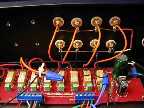
Some Parts Used
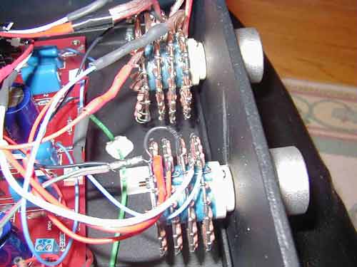
I used the Input Select board with the support from diymania.net (a Korean DIY site). It has 4 sets of RCA unbalanced input, 2 pairs of XLR balanced input and 1 Tape In. To drive this board, I use the Avel Lindberg 12V toroidal transformer as shown above. Since I do not have balanced Input device, therefore, I did not install the XLR input jack (female). I shorted the -In to GND because of not using XLR Input. You can also see the wire connection here for the inputs. I used two 10K 24-steps Attenuator for full balanced volume control (at the output side). The quality of these two attenuators is very good and not very expensive! The control is very precise. What I would like, if possible, is to have more steps than 24, but so far it is more than I can ask for, in terms of price and performance. No complain what so ever! I opted for the Elma 2 pole, 6 position selector switch. The part number is: 04-1261. This is a silver-plated version and cost about USD$28.00 (For the Hi-End gold-plated version, the part number is: 04-1264 and cost about $45 or so). The quality of this one is very good and it is a "make before break" design. If cost is your concern, Radion Shack sell a $4 selector switch and I found it to be pretty good, too!
Main Board Setup
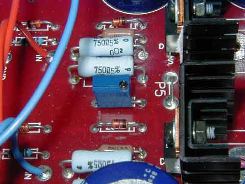
For the main board, you can download the gerber file from passdiy.com. I got the boards from the Korean diymania.net, plus the Input Select board designed also by the diymania.net. For the capacitor of C3 & C4, I am using the 3300uF/63V, instead of 1000uF/100V. I raised up all the mosfet to make them cooler with bigger heat sink (optional, there is no need to do this!). To do that, I need to connect the Drain pin to the C1 & C2, because they are electrically live. If you are designing your own PCB, make sure this is following the design. I also add the 0.47uF/250V bypass capacitors to C3 and C4 (at the bottom of the board). The resistor R15 is the coupling resistor to both Q1 & Q2. You can adjust R15's value to increase or decrease the gain. I use the 500 ohm Vishay VR to replace the fix value resistor. I use the jumper pin for P5 (and not the pot, as this is optional) and therefore the gain is about (R1+R2)/R15 I initially set my VR to 430 ohms, which will roughly gives me about 10 dB (gain is 3.48) of gain. (You must set VR value first before soldering it on). If you increase the R15 value, the gain decrease! Remember this is the gain for balanced output. (as Unbalanced output will be less gain). The gain is also depends on the efficiency of your power amp and speaker. You can adjust this value to match your system. For me, 10 dB gain is good enough for my Triangle Polaris floor speaker system (sensitivity: 90 dB). If you like the convenience, you can put the "socket pin" for the VR. By doing this, you can always pull out the VR and adjust it and then put it back. As the VR is in the series of resistors, by measuring it directly will not reflect its true value!
Installation Info
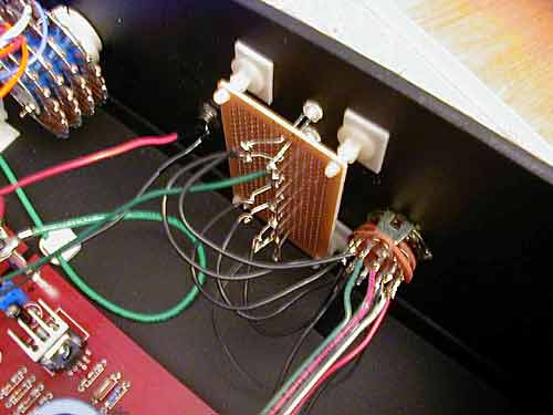
I added the Power LED in the front panel and it can also act as the Bleeder for the remaining current stored in the caps after power off. One thing to be cautious, if you are using the board made from passdiy's gerber file, you need to connect both lines in V+ and V-, as they serve different circuit path. I did my initial test without running both lines, the result is a burning smoke and a flash! I burned one zener and one resistor and it took me a day to debug it and fix it right! After the connection lines is done, power up with cautions! Measure the Drain pin again GND. It should have the voltage around +30V and the Source pin to GND should be -4V. In my case, they all are within tight 1% tolerance of these voltages. I am very happy with it! I use two 10K 24-steps Attenuators to control my output. On the output jack, I am using XLR male connector and its pin 2 share the positive pole with RCA positive pole. Both RCA and XLR ground are connected together and into the chassis ground. (I use star-ground into one ground point, for both earth ground and chassis ground!) I did not install the Input side attenuator. As for reason why, Nelson did explained in his article. I use the input selector board, so that BZLS can accept multiple sources. I do not have input balanced source, therefore, I connect the -In from both channels to the GND. I did not do this when I first test run it and there is no sound output at all! After a good while and I noticed that I need to do this and sound flow out smoothly! It was a wonderful feeling at the time you hear the music came out! I also added the LED for the input sources. The circuit is simple! I bought a circuit board from Radio Shack and connect the lines according to the figure above. It works great! (I feel that Ø3 mm LED may looks better than my current Ø5 mm LED. You can try it yourself!)
Testing
Is it good? That's first thing I wanted to find out when I finally finish it! I connect it to my McCormack DNA-0.5 power amp. The sound simply surprised me greatly! I have a "precious" Audible Illusions L1 pre-amp then. I decided to sell it because of this BZLS! I brought my BZLS to my friend's house, who has a pair of Aleph 2. The sound now feels a little bit on the hard side. I hope once I burn-in the machine, the sound will be more soften! A month later (Jan. 2004), I finish my Aleph 5. Now I am using my Balanced Zen with my Aleph 5. Both machine are in burn-in mode now. I hope I can share with you a few months later how the sound goes then!
You can find my full DIY journal at this link: http://www.penguinlovers.net/audio/bzls_proj.html
Credits
Nelson Pass: Many thanks for your wonderful design and generosity to share your intelligence!
Boards are supported by diymania.net. Case from ACSP in Taiwan.
Russell Sun: My friend who taught me all things about Audio and he is the person who persuaded me to buy my first amp and speaker!
My family's support in DIY hobby!
Thomas Chao
.(JavaScript must be enabled to view this email address)