Miscellaneous Projects
My DIY Project
I owned a commercial Amplifier 3 and love the sound of it. I started the DIY because it is my dream hobby, plus I would like to make a higher power amp with balanced input. This A5 seems to be a perfect DIY project for me. I have already finished my Balanced Zen Line Stage about a month ago. BZLS is also a very good design from Nelson Pass. The sound of it surprises me! I am planning my next project after A5 will be Amplifier P 1.7 pre-amp, which is similar to BZLS, but should be significantly better! Thanks to Nelson Pass for sharing his wonderful design to the DIY world! None of this will happen without your intelligence and your generosity!
The Parts List
The Parts list I used is posted here (in MS Excel format). I separated the required parts and optional parts (I used). The part number and pricing from both Digi-Key and Mouser are only for your reference (it is good to calculate the cost!)
The Case
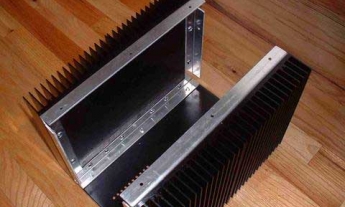
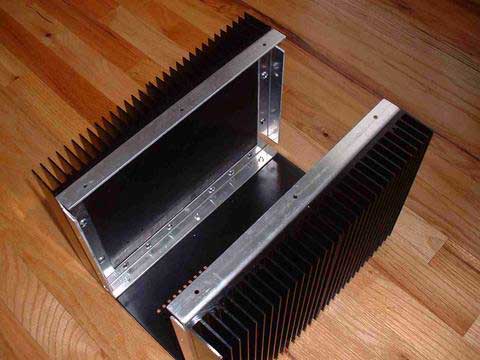
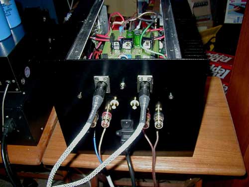
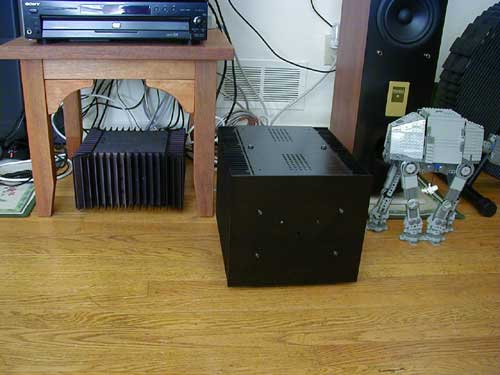
I purchased the case from Taiwan (group purchase). The case is originally designed for Amplifier 2 mono block. I just roughly guessed that it might fit A5. It did, but it's kind of tight! The case is pure vanilla one and it only came with AC IEC outlet hole. I have to drill the holes for XLR, RCA, Speaker post, fuse and power switch. Drilling the XLR holes is really tough job to do! I am glad that the holes came out pretty good! (It is all done by hand-held drill. If I got a drill press, I believe it will have a better result!)
Matching the MOSFETs
I matched all input MOSFET IRF9610 (Q1 & Q2) 0.01V. Q3 does not need to be matched, but I still use the nearest value I can. I purchased 20 pieces and I can easily match what I need for my A5.
For the Power and Bias output MOSFET, IRFP240, I matched them down to 0.01V. I purchased 40 pieces and I can easily get the 4 x 3 pairs for my A5.
There is an article about how to do the matching from Nelson in here. There is also a discussion forum for matching the device in diyaudio.com and you can refer it here. The resistor I used is 2.2K. 500 Ohms is also fine. When matching, make sure to test it until the digits stabilized! I tested each one for about 20-30 minutes each.
Power Supply Section
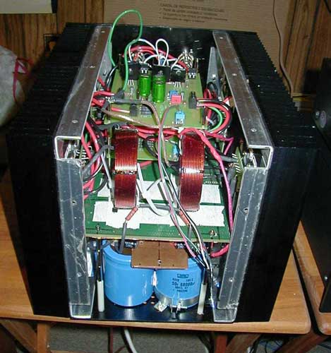
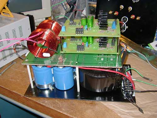
I mounted the bridge rectifier on each side of the heat sink. This will help the rectifier to cool a little bit! The capacitors is fixed in place by two capacitor clamps. I used a Plitron 750VA/2x25V (Part number: 107016201. If you order it, be sure to order the mounting kit also, because it is not included in the price!). The quality of this toroidal transformer is very good! It is better to use 2x28V, but Plitron provides free Magnetic Shield upgrade to the 25V transformer. I calculated it's value and thought it should provide enough rail voltage! It turned out I got +/- 36.6VDC before the load. By adding the load, I got +/- 33.6V, which is close to the +/- 34V in the A5 schematic. I am happy about this! I choose to use the dual bridges design and use only 1 transformer, due to the size of the case. The capacitors I used are 4 Nippon Chemi-Con 68,000 uF/ 50V. I purchased it at a very good price with my friend. For the PSU bypass capacitors, I use two 4.7 uF/100Vdc cap, but later changed to 0.47uF/400V ERO MKP cap. I use a 2mm thickness, pure copper plate for the common connection among the 4 capacitors. It also help fix the capacitors in place! I study the power supply circuitry a little bit and I choose to use what most people use, the Pi CLC PSU. By adding the CLC, it is a very useful in reducing the ripple. I compare the original design and later choose the design from Kristijan Kljucaric. You can refer the design here. The Inductors are 2.2 mH. Kristijan also made other Amplifier PCB for DIYer. The Inductors should be placed as farther as you can away from the low level Input signals and isolate the bare wire from chassis. You can also use CRC (using 0.5R/40W resistor, for example) to lower cost a little bit, but I considered the Amplifier's current is higher than a CRC circuit can handle with good result!. I use two CL-60 Inrush Current Thermistors and the Thermostatic switch rated at 75C. I use Star-grounding to connect all grounds (earth ground and chassis ground) into one spot. The result is very good. The amp is very quiet in the background! I did wanted to add the Speaker delay relay circuit, but the space had limited my choice! I had to give it up, instead, I always turn the volume to minimum on pre-amp to prevent signal spike when turning on and off of the amp. I saw one user use a toggle switch for the speaker. I prefer the cleaner signal path as I can! Therefore, I leave it as-is in the original design. One thing to remember is always add the Bleeder Resistors to the large capacitors. It is for safety reason. I use two 10K Philips 3W precision resistors. To calculate the resistor, this is a quote from the diyaudio: "you can calculate the time (t) your supply caps can be bled by using the formula t=RC; where t=seconds, R=resistance in ohms, C=capacitance in Farads. Or the bleeder resistance for that matter. So if you have a 25,000 uF of cap and you would like 15 seconds of discharge time, your R=t/C. I don't have a calculator right now (at a public library). Power (P) dissipation of the resistor will be P=V^2/R. V is the unreg supply voltage. Double P value of the resistor...this will get hot. You can use this resistor before working the innards of your amp so you can bleed off stored energy and avoid a nasty spark or shock."
Main Board Setup
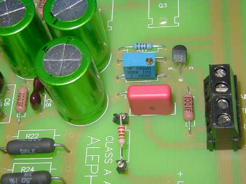
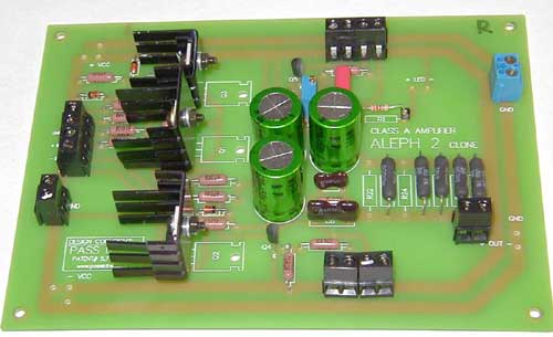
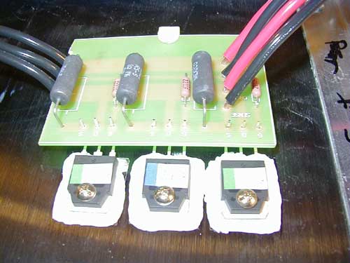
The board I use are from a group purchase. The board is based on Brian Bell's Amplifier 2 board design with a little circuitry modification. I also have changed some parts to fit for A5. I use 3 Nichicon Muse ES Bi-polar 220uF/50V capacitors for C5, C9 and C10. All resistors are Dale 1% resistor. For C7, I use the Wima 0.047 MKP capacitor. The output resistors is a series of 5-0.5 ohms/3W resistors, instead of 4-0.47 ohms resistor, because they are out of stock when I ordered them. Actually, you can use the same board for all Amplifier series amp as long as you change the appropriate parts. For the resistor R19, I changed it to use the Vishay 500K ohms VR. This gives me the advantage to adjust the bias voltage on the output board. For Q4 and Q5, the most common error is when using other common transistor, the pin setting might be different from the MPSA18. Make sure you notice that, if you want to use other kind of transistor! This tiny difference may cost your amp and it is sometimes hard to debug! R1 is original at 10K. I changed mine to 2.2K for my blue LED. Our group purchase also made the Bias and Output board, instead of p2p. I feel this is more organized than the p2p one. The IRFP240 is the TO-247 package, which has the plastic around the screw hole for isolation to the chassis. This saves me from using the transistor mounting kit. I use the mica insulator plus the thermo paste to mount the mosfets. All output board wire are 12 ga, OFC power wire. I found an old PCB to use it to hold the Inductors, the 2 channel boards and serve as the shield from the transformer. I plated a sheet of copper as the shield at the bottom of the PCB and ground it. I also put a layer of paper tape for isolating the potential parts that may cause the problem of un-intentional short from the PCB!
Installation Steps
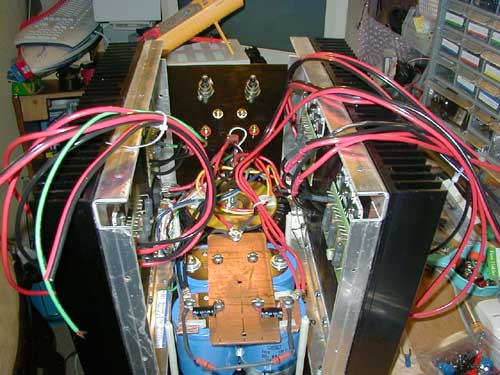
After the PSU is tested and approved, I started it by assembling the case and then put the PSU in place. The heat sink on both side is then added on to it. A simple job of tightening the screw can be quite challenging, in a tight space like this one! In the service manual, the original A5 shipped with the XLR shorting jumpers. As I search locally and on-line, I was not able to find where to buy this U-shape shorting jumper for the XLR, when using the unbalanced RCA input. (as for why to this, check this info link). For this reason, I decided to use a toggle switch to toggle between full balanced mode and unbalanced mode. The concept is simple. If you are using the unbalanced input, all you have to do is to jump the pin 1 (GND) and pin 3 (- In), as normally a shorting jumper will do! (The European and some Asian XLR setting might be different. I believe, is to short the pin 2 & 3!). Also by doing this shorting jumper, you will gain back 6 dB! This is particularly good if your pre-amp is the weak link! The steps I install mine are:
After I completed the Power Supply and measured the output, which is around +/- 33.6V in rail after adding the load (NP's design is +/- 34V). I added the Bleeder Resistor, as the high capacitance of the capacitors is used (for safety!).
(Optional) I checked the AC ripple and it shows that the CLC filtering is working good!
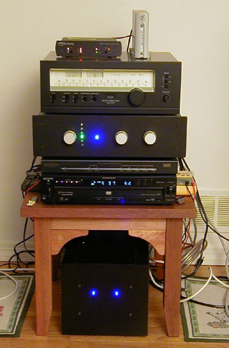
Connect the Blue LEDs. I used the 2.2K for R1, because of the lower mA blue LED I choose. I connected the Power and Bias board on one channel and measure the bias voltage. It should be 0.5V, according to Nelson Pass' design. In my case, both channels are around 0.620V and the blue LED lit up OK, not too bright, not too dim!
I adjusted the R19 VR, so that the Bias voltage is around 0.5V! Some suggest using (R19) VR for initial adjustment, then take it off and replace it with the fixed value resistor, as this will improve the sound quality! This option is entirely up to you. I picked to use the VR for convenience's sake!
I checked the following voltages to verify my installation. At Q3 (R11), Q4 (R14) and Q5, it should be 4 to 5V. Q1 and Q2 Source to GND should be +4V. I have all the voltages right! Half of my worry is gone right away!
Once one channel is done. I connected the other channel and repeats steps 3 to 5. I am lucky that the second channel also have all the voltages right and I only need to adjust is the R19 to make all output resistors close to 0.5V bias.
Now comes to the time to test the sound output. If you use RCA Input only, make sure to ground the XLR connector's pin 3 and pin 1 (if you don't do this, the difference is a loss of -6 dB).
Run-in the A5 for 1~4 hours and measure all the voltages again, make sure they are all correct and check the temperature of the heat sink. They should be less or around 70ºC (or 158ºF). In my case, they are about 55ºC to 60ºC after 1 hour. The T1 thermostatic switch should kicks in and shut the A5 off, if the temperature exceed 75ºC. Check each bias voltage multiple times after each couple of hours of listening for the first week.
Testing
I did a careful study and planning before I start building. I am lucky that all are doing well according to my plan, actually better than I expected! (In comparison, I burned 1 Zener diode and 1 resistor when building my BZLS, which took me a day to find it out!) This is my first test with my Balanced Zen Line Stage pre-amp. I am using the Balanced XLR interconnection. The DC offset of my A5 settled at 56 mv for left and 46 mv on the right channel after about 1 hour. So far, the hight tune is good. Mid-range also is very good, but the bass didn't impress me yet! One DIYer shared his experience using 1.0uF/50V Black Gate N-type cap on Z5 as bypass and that the sound is very good for both high tune (bass remains the same)! I did the fine tuning on my A5 by changing the PSU bypass cap from the 4.7uF/100V Electrolyte capacitors to ERO MKP 0.47uF/400V. I also added the bypass cap on Z5 using the WIMA 1uF/63V MKP capacitors. The sound seems to be more precise and with more concentration. My first impression to the sound that it is very similar to my [genuine] Amplifier 3 and I am yet to find out the difference of the two! After 3 months, the sound is more open and sound stage is more clear than before.
Credits
Nelson Pass: Many thanks for your wonderful design and generosity to share your intelligence!
Brian Bell's PCB layout and PRBS in supplying the boards. Case from ACSP in Taiwan.
Russell Sun: My friend who taught me all things about Audio and he is the person who persuaded me to buy my first amp and speaker!
My family's support in DIY hobby!
You can find more details of my A5 DIY journal at this link: http://www.penguinlovers.net/audio/A5_proj.html
Thanks,
Thomas Chao (question e-mail: .(JavaScript must be enabled to view this email address))
a5-p13-f1.jpg (24991 bytes)
a5-p13-f2.jpg (39275 bytes)
a5-p13-f3.jpg (39605 bytes)
a5-p13-f4.jpg (34551 bytes)
a5-p13-f7.jpg (25375 bytes)
a5-p13-f8.jpg (25547 bytes)
a5-p13-f9.jpg (25296 bytes)
a5-p13-f10.jpg (41119 bytes)