Miscellaneous Projects
I like to call them A4.5 monoblocks because they are something between A4 and 5.
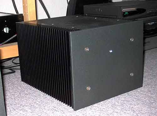
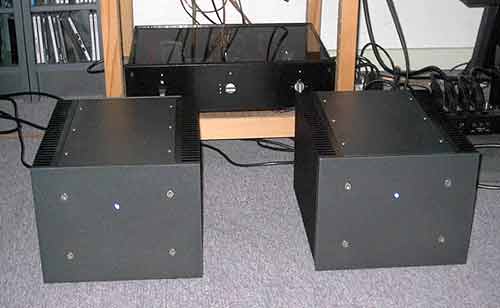
After more than one year I managed to finish my two Amplifier Monoblocks. Some will think, how could I wait so long. Better late, than never I always say. The mechanical construction was the hardest part. I barely had any fun with this part. The whole construction has too many screws that all have to be mm exact or nothing will fall in place. Fortunately I had enough experience with other DIY amps so the end result is very good. The boxes look really cool. I used 3mm Aluminium parts for top, bottom, backplate, middle separator and 5mm for the front plate. The coloured parts were made from a painting company with the electrostatic method. The colour is a metallic dark grey.
The technical stuff:
I wanted a little more power than the 60-Watts from the Amplifier 5 and the 100 Watts from the A4 were too much to cool. The boxes would have to be really big. My idea was to make something a little bigger than the Amplifier 5. I used 8 power Mosfets in each channel and increased the voltage rails to +/- 41 Volts. That's what I got from a 2x30Vac toroid. I haven’t measured this yet but theoretically the Amplifiers should be capable of giving 80 Watt RMS into an 8 Ohm load. The Amplifier 5 uses 6 Mosfets and gives 60 Watts that's 20 Watts for every 2 Mosfets. So I used 2 more to get to 80 Watts. I also had to give more voltage for the output voltage swing.
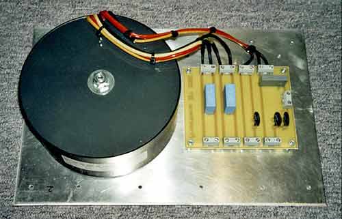
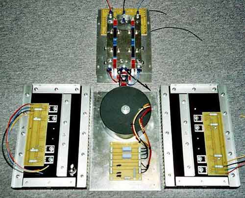
The Power supply has a high end 600 VA toroid with 2x30 Vac secondaries.
This toroid is magnetically screened and has a screen coil between primary and secondary.
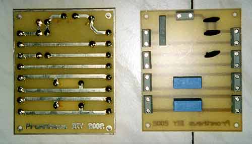
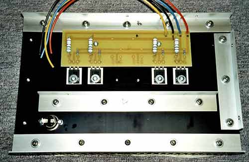
I use a special PCB for the power connections. This PCB has all the Toroid cables, the mains cables, the mains and secondary filter caps, the ground and inrush current thermistors and also a connection for the 75°C thermal switch. You can see this in one of the pictures.
I used one 35A bridge with 4 x 0,047 MKP WIMA caps across the diodes and than 4 x 22mF, BC 154 Components, high current Capacitors with 4 x 1,5uF WIMA MKP caps parallel to them.
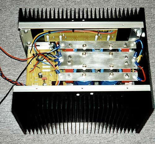
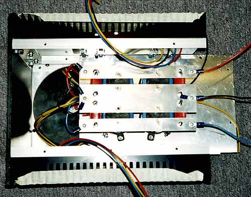
I used IRF610 and IRF9610 on the main PCB and IRFP240 for the output Mosfets. All Vgs of Mosfets were measured and made into sets of four. This took a long time because I waited 3 minutes for each Mosfet to stabilize temperature. I found out that the time you have to wait has to do with the heatsink you use for the measurement. Keep the heatsink always the same temperature and you will see there is no change after 1 minute.
All the above are for one channel.
The heatsinks I used are the SK56/200/SA from Fischer in Germany. They are 300mm X 200mm X 40mm. They have a thermal resistance of 0,30°C/W. I use 4 heatsinks, each one will cool 4 Mosfets. You shouldn't use anything smaller or it will get too hot. My heatsink get very hot but I can still touch them. In the summer I hope they don’t get too hot.
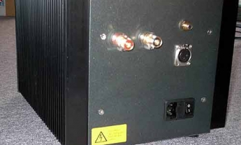
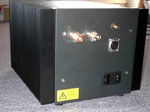
As you can see in the pictures, the front has only a Blue LED power indicator. The back contains all input and output connections. You can see the IEC mains connector with fuse and switch, one Neutrik XLR for balanced input, one Cinch gold plated for the single ended input and the two fully isolated output connectors for the speakers. To make the Amps smaller I used a second bottom over the toroids for the rest of the parts. Here you can find the bridge in front, than the big Caps and behind the main PCB. Almost all cables start from here. I used PCB strips to connect the big Caps with screws, the MKP caps are soldered and the Cables are fastened with M3 screws.
First impressions:
Unfortunately I don't have any good speakers at the moment. I am still constructing them. So I can't really enjoy these amps yet. I can say that the sound quality of the Balanced Line stage with the Amplifier amps is a lot clearer and of course louder than my small Harman Kardon amp. I have a lot more bass now and the middle and highs are a lot clearer. The amps get very hot but I can keep my hand on it so I guess that's less than 60°C. It gets so hot I think after one hour. I checked after 6 hours of continued function and it was the same.
I am really pleased to have made such an amp. I always thank Nelson Pass for this great inspiration in DIY. I would have lost interest a long time ago in DIY Audio if it wasn't for his great articles in Audio Electronics and AudioXpress. Also I would like to thank one more time Mark Finnis for his great PCB layouts I used. Also thanks to the many people who show their projects here in this website. It's always interesting to see, what other people experience and build.