Miscellaneous Projects
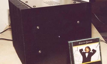
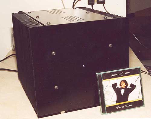
It is not too exciting to look at, but maybe the story of its construction is worth reading. I built it on a small section of my kitchen counter. Apartment living has its drawbacks.
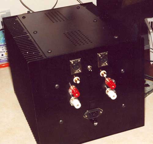
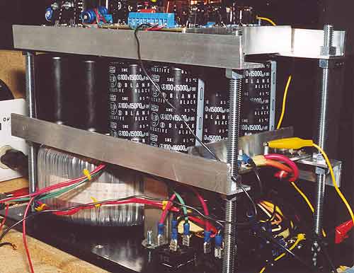
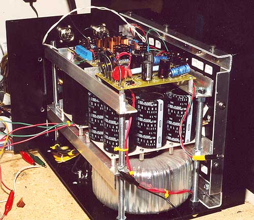
Picture captions: Build 1, Build 2: shots of PSU and boards mounted. Build 3 One channel and one end attached Rear - yep, it has connections Front - the Blue LED is on, though you cannot tell.
Looking forward to attaching my PassDIY logo to this amp.
Thanks for a fun project. An AX is on the horizon.
Bob Ellis
The story:
I remember thinking that I'd like to build the A-75 way back when the article was first published. I started collecting parts over 5 years ago. I had started a 4-channel Leach amp when I stumbled onto the Pass Labs DIY page (when it was still part of the commercial page.) I had bought a couple of massive toroids, 2 x 42@11 amps for the Leach amps. Hmm. 75 Watts ought to be plenty, but since these are going to do double duty as HT amps why not bump the rails up to get more power?
I used IRFD210/9210 for the input differentials, figuring that I'd get a little safety factor with the higher voltage rating, and lower input capacitance wouldn't hurt, either. I bought two sets of Old Colony boards (front end & PS). I planned to use one as a line stage, but when it came time to buy parts, hey you probably need to buy a bunch of IRFP240/9240 to get two matched sets, so why not buy enough to build two stereo A-75s and biamp?
I bought three sets of 12" x 4" x4" forced air heat sinks at Apex Jr. Used one for my 4 channel Leach amp, and planned to use the other two for the A-75s. I built up the front end boards. There are two spots labeled R24 (one being R81), but nothing a bit of trace following couldn't fix.
At the time I finished the front end boards I didn't have an oscilloscope or Variac. I fired it up first with a 12 volt transformer to verify basic operation, then used a 30 volt transformer to run it at +/- 50V. Boy, are those CCS trimpots sensitive! If I were to do it again, I'd go for multi turn types. After setting the offset and bias, I swapped in 12 volt zeners for the 9.1 volt reference in the power supply to bring the rails up to +/-65V. I figured that 84 VCT for the output supply would give me 55 volt rails, so I wanted the 10 volt margin of the original design.
The IRFD210's seemed pretty hot. I expected that the dissipation would be up around ½ watt (they are rated at 1 watt) but they were too hot to touch. As a preamp, it sounded very nice. It was motorboating at first, but moving the power leads cured that. I read on DIYaudio.com that I should add local bypassing for the power supplies, but didn't do anything about it yet. I soldered copper tabs on the drains of the inputs to cool them.
The project stagnated while I considered my options for a case and output stage. Work kept me away from it, for a while, too. I started drilling and tapping the heat sinks for the output FETs. Broke a tap and got frustrated. Then I found a case group buy at DIYaudio and bought two - never did like the idea of a fan. It was a bit smaller than I had planned, 8"w x 14"d x 10"h, but I figured that I could squeeze everything in there.
After much tinkering with the transformers, caps and boards, I finally figured out how to make it all fit on three levels. I'd planned to add a soft start internally but there wasn't room. I used 6 15,000 uf/100 Volt caps per channel, 45,000 uf per rail. (Apex Jr. again) They are 2"d x 3" high. So they have a level to themselves. I also added a small 60VCT transformer for the regulated supply, figuring that the doubler running off 84VCT would put the regulator dissipation too high and threaten the doubler capacitors.
Along the way I purchased a used O-scope, a Powerstat and a drill press. Projects are an excuse to buy tools, right?  When I got the first case assembled the scope came in handy. Without bypassing the power leads I was getting a nice 140 KHz oscillation that went away with a mere 0.1 uf across the power leads to ground. To play it safe I added the 200-uf caps I had handy, too. Oops, got one backwards. Mr. Powerstat allowed me to keep it from popping, but it was a goner.
Without the oscillation, the input FETs were just comfortably warm with 64.8 V on the rails. Since I'd had some trouble adjusting the bias and offset with a 1KHz input tone (my computer tone generator has a DC tick) I didn't try to use a tone on this board. I'd listened to the other one, but not this one.
I hooked up the first outputs, and everything went smoothly. I used 6 Fairchild IRFP240/9240 per channel, wired point to point. I was a little surprised at how slowly the bias came up when I first cranked up the bias pot. After some fiddling (hours chasing it even using the go halfway to where you want it method), I got it stable at 1.2 Amps total and the DC offset down to .010V. Next channel. It went a bit faster because I didn't let the bias overshoot on the high side. The bias really climbed when I laid the top on the case, so I spent some time getting it down.
This 84VCT transformer gives me 60 volt rails when loaded to 300 watts. I figured I'd be able to run about 150 watts idle dissipation to get a case temperature around 50C. I measured 40C C at that level, so I can take it up another 50 W/channel later.
I got a test tone CD, so once the bias was stable I put a signal to it. Hmm - one channel nothing and the other an attenuated signal. The phone rang, I was on the phone for a bit and POP! The channel that had a signal blew most of the output transistors. The 10 amp line fuse was not just blown, it was plated onto the glass.
Well, the channel that had no signal had a cold /broken joint on the wire from the RCA jack to the XLR. How often does a bad connection SAVE work? After disconnecting the outputs I verified that the front end boards were still working. At least they didn't burn up. They didn't amplify - the signal out was about 75% of the level going in. However, at the drive terminals there was a 7 volt signal for .2 volts in. Have you guessed my mistake yet?
I chose to start with a jumper for R81 and take full feedback from the output stage. Unfortunately, I swapped the jumper and R27 (75K feedback) resistor when stuffing the board. OK, now we know that the amp doesn't like being driven at unity gain. (The input network drops the signal level slightly, hence the attenuation observed.)
I was frustrated and nearly gave up on the project. Saturday was relatively warm for Pennsylvania in January. So I went for a bicycle ride to clear my head. I went further than I had planned, and the temperature dropped to 40 during the ride. Feeling better, but tired, I began rebuilding.
I used the other main board, verifying that it amplified and otherwise worked. After matching output devices, I had put them back in the tube in Vgs order. I picked six 240s and six 9240s matched within .011V. After installing, I began re-biasing. The undamaged channel biased up fine. The second seemed to come along, although one end of the heat sink seemed hotter than the other. The chassis is too tight to check all the source resistor drops, so I just measured at one end - the cold one. I wanted to hear this thing, and after half an hour the bias seemed stable so I hooked it up.
I heard lots of detail, but the right (funky heat distribution) channel seemed grainy. Maybe it's this CD, as I got up to put another CD on, POP! FZZT! And the magic smoke came out again. It was nearly midnight (I don't normally stay up that late), so I disassembled it far enough to notice that two FETs on the hot end had melted somewhat. I had stuck the Vgs labels above each FET for reference ("in case" I blow one.) Oops. Yeah, the last 2 digits were close, but the 3.484 and 3.581-3.593 aren't a really good match, especially with 0R22 source resistors. Current hogs had gone wild - enough thermal mass to keep them alive for a while, but not long.
I considered increasing the source resistors, but didn't. The next morning I managed to get replace the blown FETs and get it reassembled for biasing after verifying that the current sharing was reasonable. I set it for 150W dissipation per channel and buttoned it up. Oddly, after tightening down the top and rear panel (3mm aluminum) the heat sinks are significantly cooler. I am not sure if this is due to the panels helping the heat sinks or the now more stagnant air causing the bias to drop (the case is ventilated, but not much). Perhaps I'll open it up and run leads out to measure the bias in the sealed state and crank it up accordingly.
Well, it finally keeps the smoke inside, where it belongs. I am glad I bought enough output devices to allow me to get several well matched sets. Assuming I pay attention on my second one, I'll have enough left over to do a pair of low power Alephs or my AX.
I didn't use any exotic components. I even used sand source resistors (I can hear the resistor police coming.) I used full feedback from the output stage (R81=0), and the folded cascade configuration. Had I built it in a larger chassis I might experiment, but it is too much work pulling this thing apart to mess with it now.
The amp now sits in my living room with it's blue LED glowing (a little too) brightly. Detail without harshness, bass with authority, a blacker background. I started with a few of my Zappa CD's in honor of Mr. Pass, very nice. I might be moving to Montana soon… I don't have any Goldfrapp, and my local CD store doesn't either. I have gone through a variety of music, enjoying all the newly found nuances. The amp seems to show its best with simply recorded acoustic music. All the room ambiance is there now. Music just sounds better than it did before, even the radio sounds better somehow.
This was supposed to be #1 of two, but encouraged by the sonic improvement, I'll probably go for an Aleph or AX as the top end of my biamp system. The journey continues….
Thanks to Mr. Pass and Mr. Thagard for sharing this design.
Robert.
When I got the first case assembled the scope came in handy. Without bypassing the power leads I was getting a nice 140 KHz oscillation that went away with a mere 0.1 uf across the power leads to ground. To play it safe I added the 200-uf caps I had handy, too. Oops, got one backwards. Mr. Powerstat allowed me to keep it from popping, but it was a goner.
Without the oscillation, the input FETs were just comfortably warm with 64.8 V on the rails. Since I'd had some trouble adjusting the bias and offset with a 1KHz input tone (my computer tone generator has a DC tick) I didn't try to use a tone on this board. I'd listened to the other one, but not this one.
I hooked up the first outputs, and everything went smoothly. I used 6 Fairchild IRFP240/9240 per channel, wired point to point. I was a little surprised at how slowly the bias came up when I first cranked up the bias pot. After some fiddling (hours chasing it even using the go halfway to where you want it method), I got it stable at 1.2 Amps total and the DC offset down to .010V. Next channel. It went a bit faster because I didn't let the bias overshoot on the high side. The bias really climbed when I laid the top on the case, so I spent some time getting it down.
This 84VCT transformer gives me 60 volt rails when loaded to 300 watts. I figured I'd be able to run about 150 watts idle dissipation to get a case temperature around 50C. I measured 40C C at that level, so I can take it up another 50 W/channel later.
I got a test tone CD, so once the bias was stable I put a signal to it. Hmm - one channel nothing and the other an attenuated signal. The phone rang, I was on the phone for a bit and POP! The channel that had a signal blew most of the output transistors. The 10 amp line fuse was not just blown, it was plated onto the glass.
Well, the channel that had no signal had a cold /broken joint on the wire from the RCA jack to the XLR. How often does a bad connection SAVE work? After disconnecting the outputs I verified that the front end boards were still working. At least they didn't burn up. They didn't amplify - the signal out was about 75% of the level going in. However, at the drive terminals there was a 7 volt signal for .2 volts in. Have you guessed my mistake yet?
I chose to start with a jumper for R81 and take full feedback from the output stage. Unfortunately, I swapped the jumper and R27 (75K feedback) resistor when stuffing the board. OK, now we know that the amp doesn't like being driven at unity gain. (The input network drops the signal level slightly, hence the attenuation observed.)
I was frustrated and nearly gave up on the project. Saturday was relatively warm for Pennsylvania in January. So I went for a bicycle ride to clear my head. I went further than I had planned, and the temperature dropped to 40 during the ride. Feeling better, but tired, I began rebuilding.
I used the other main board, verifying that it amplified and otherwise worked. After matching output devices, I had put them back in the tube in Vgs order. I picked six 240s and six 9240s matched within .011V. After installing, I began re-biasing. The undamaged channel biased up fine. The second seemed to come along, although one end of the heat sink seemed hotter than the other. The chassis is too tight to check all the source resistor drops, so I just measured at one end - the cold one. I wanted to hear this thing, and after half an hour the bias seemed stable so I hooked it up.
I heard lots of detail, but the right (funky heat distribution) channel seemed grainy. Maybe it's this CD, as I got up to put another CD on, POP! FZZT! And the magic smoke came out again. It was nearly midnight (I don't normally stay up that late), so I disassembled it far enough to notice that two FETs on the hot end had melted somewhat. I had stuck the Vgs labels above each FET for reference ("in case" I blow one.) Oops. Yeah, the last 2 digits were close, but the 3.484 and 3.581-3.593 aren't a really good match, especially with 0R22 source resistors. Current hogs had gone wild - enough thermal mass to keep them alive for a while, but not long.
I considered increasing the source resistors, but didn't. The next morning I managed to get replace the blown FETs and get it reassembled for biasing after verifying that the current sharing was reasonable. I set it for 150W dissipation per channel and buttoned it up. Oddly, after tightening down the top and rear panel (3mm aluminum) the heat sinks are significantly cooler. I am not sure if this is due to the panels helping the heat sinks or the now more stagnant air causing the bias to drop (the case is ventilated, but not much). Perhaps I'll open it up and run leads out to measure the bias in the sealed state and crank it up accordingly.
Well, it finally keeps the smoke inside, where it belongs. I am glad I bought enough output devices to allow me to get several well matched sets. Assuming I pay attention on my second one, I'll have enough left over to do a pair of low power Alephs or my AX.
I didn't use any exotic components. I even used sand source resistors (I can hear the resistor police coming.) I used full feedback from the output stage (R81=0), and the folded cascade configuration. Had I built it in a larger chassis I might experiment, but it is too much work pulling this thing apart to mess with it now.
The amp now sits in my living room with it's blue LED glowing (a little too) brightly. Detail without harshness, bass with authority, a blacker background. I started with a few of my Zappa CD's in honor of Mr. Pass, very nice. I might be moving to Montana soon… I don't have any Goldfrapp, and my local CD store doesn't either. I have gone through a variety of music, enjoying all the newly found nuances. The amp seems to show its best with simply recorded acoustic music. All the room ambiance is there now. Music just sounds better than it did before, even the radio sounds better somehow.
This was supposed to be #1 of two, but encouraged by the sonic improvement, I'll probably go for an Aleph or AX as the top end of my biamp system. The journey continues….
Thanks to Mr. Pass and Mr. Thagard for sharing this design.
Robert.