Miscellaneous Projects
Enclosed please find some pics/drawings of my A3 clone.
As a mechanical engineer, my electrical knowledge was just enough for me to handle some simple check of my house appliances. Until I discovered some very informative websites like "PASS DIY", and "DIY Audio.com", I started to believe that to DIY audio gears is also possible for someone like me. And the most important, DIY audio gears can also be high performance ones. I want to thank you and all those DIYers who contribute/share a lot of information on net. Especially I respect you as an audio specialist with fully self-confidence, as you publish your design on net. I believe there are also audio specialists out there, but none of them could do so. Thank you!
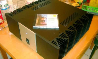
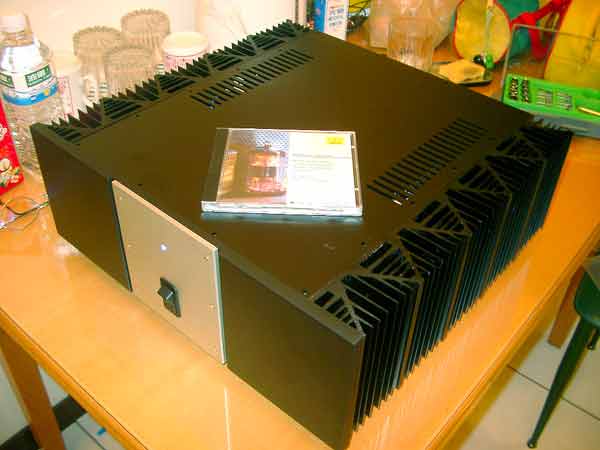
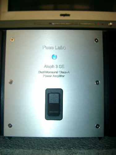
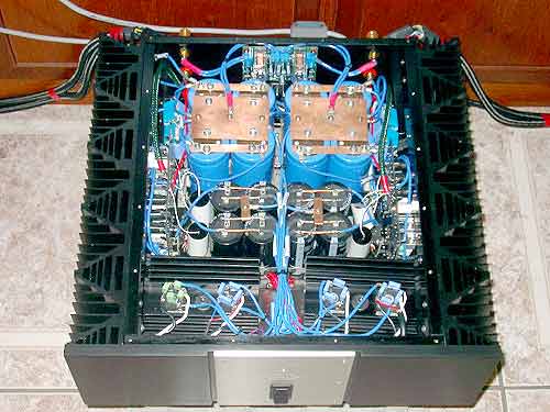
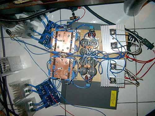
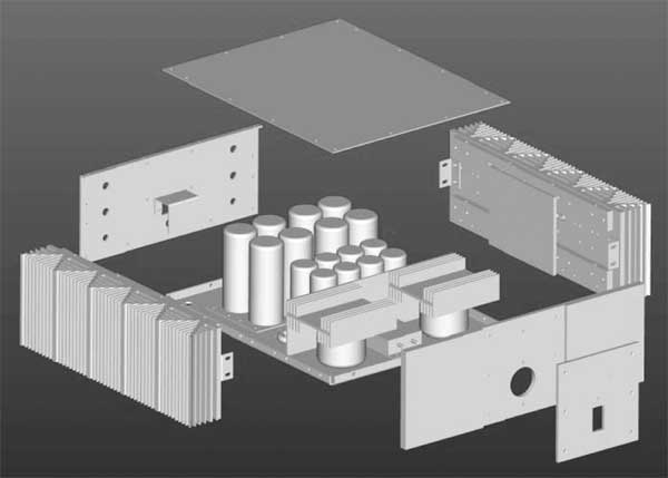
The idea to have a DIY project of a Class A amp dates back to March 2002. At the beginning stage, most of my work was only studying (electrical diagrams, parts, wiring,...). After reading tons of materials, A3 was chosen because of it's simple design and high audio performance (simple is good, isn't it?). In September 2002, orders were made to different suppliers around the world (not every part can be found in Taiwan). In October, this little baby was born (Pic 1). I connected this "amp" to my system and the performance was amazing. I run this "amp" as it was for two months, while I was preparing a "chassis" for it. At this stage, I am very happy to be a mechanical engineer. The design of the chassis is straight forward as you can see on the drawings (computerized by a friend of mine, Miss Yi-Pei Shih). But, of course, the WAF (wife acceptance factor) had been taken into account, heavily.
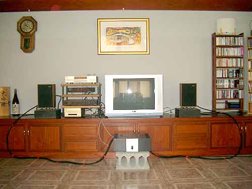
The performance of this amp is amazing. Hum can be hear only if stick your ear on the speaker. Music is very natural and detailed. Bass is tight and bouncy. Dynamics? Oh, yes of course! I couldn't believe my little Spendor speakers can be this good. Now I can listen to the CDs for a long time without fatigue. But obviously, I need a new pair of better speakers now.
Technical data:
Dual Mono design
Rail voltage: +/- 26V under load
Bias: 1.1A per transistor
DC output: 75mV/ right ch, 10mV/left ch.
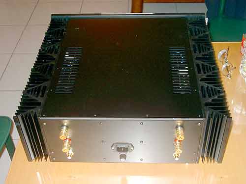
Dimensions: 430mm x 400mm x 150mm (W x D x H)
Weight: 25 kgs
Power supply, per channel
300VA toroid transformer x 1, Pri:110V, Sec: 0-21V, 0-21V, shielded
Bridge rectifiers: IRF 36MB60A x 2, crossed by 0,01uF PP caps
Filter caps: 22,000uF x 4, Nichicon
10,000uF x 4, Sprague
Speed up caps: 4,7uf PP cap x 2, UCC
2,2 uF metal film cap x 2, Philips
2,2 nF metal film cap x 2, Rifa
Choke: 2,7mH common mode choke x 1
On PCB, per channel:
Transistors: IRFP244 x 4, International Rectifier
IRF9610 x 3, International Rectifier
MPSA18 x 2, International Rectifier
Zener diods: 9,1V, Motorola
Resistors: 0,5%, Holco 0,5W
Power resistors: 0,47ohm x 4, Fukushima 5%, 5W
Caps: 220uF/25V x 3, Black Gate FK series
1nF x 1, Wima
As you can see in the pics, there are five heatsinks per channel. Two of them (no.2 & no.4) with two transistors on each. Additionally, there are four aluminum bars across those 5 heatsinks. These aluminum bars transfer heat from the two heatsinks, which with the IRFP244s on it, to the others. The temp is stabilized around 55 degree C (room temp about 20C), which is quite a good result for 200W heat dissipation.
This is my first DIY project and I'm now very happy with the results I get (even though I believe I spent the money more than it needs). Moreover, I learn a lots about electrical which I was lack of. My old CDs sound different now. I need to spend a lot of time to go all over again --- with pleasure.
Greetings from
Jesse Hsu, Taiwan