Miscellaneous Projects
The first thing I want to do is thank Nelson Pass and the rest of the crew at Pass Labs for their support of the DIY audio community in general, and myself in particular. There are many audio enthusiasts who don’t have the background in analog electronics design to enable them to take on projects of this nature without the basic electrical design work already completed. Having basic designs for high quality, high resolution electronics available on the web helps the hobby in a very positive way. There are probably hundreds of Pass amps being built all over the world - this is seen by browsing through the “project gallery” on the Pass Labs website.
About my project
This particular project as far as I can tell is the first implementation of an A2 to be published. It appears that there are several others actively engaged in producing A2 amps and there may be many more already completed.
The A2 is a 100W Class A monoblock amplifier that idles at about 300W. The circuit is single ended in that the drive can only pull the output to the negative voltage rail - the positive going signal edge is powered by a patented constant current supply from the positive voltage rail. The sound is stunning for a DIY effort - very clean and liquid. The mids are open and well defined, the highs are clear, and the bass is very powerful. The amp has excellent detail retrieval and generates a large and quite deep soundstage. I don’t consider that I am a good critical listener yet - it is something I’m learning, so I’m not good with all the happy words from the magazine writers. What I can tell you is that I’m enjoying my brand new CD collection. The amps are that good. I can hear subtle sounds in recordings that I’ve never heard before such as the decay in ringing sounds, the initial attack of a steel guitar string when it is released. The steely ringing sound of those same strings after the release is very evident. Using the “Ultimate Demonstration Disc” from Chesky records is very instructive in listening tests. There are lots of new things that you notice when you first listen to an amplifier of this quality.
The Building Process
Building the amps was not particularly difficult and the result is frankly quite a bit better than what I had hoped for. This is not to say I had any doubts about the Pass Labs implementation of the design - I was concerned about my ability to create an acceptable copy of the design. The largest problem for most who may want to also build an "A" amp will be the time required to complete the project and a basic mechanical aptitude since most of the project involves the building of the chassis. There is no single task that alone was overwhelming; rather the project as a collection of smaller tasks adds up to a significant effort.
If you are new to the hobby or are not already an expert in electronics, I would advise you to start with a smaller and more simple project than a power amp. The “Bride of Son of Zen” preamplifier is an excellent vehicle to help you learn about how to build electronics. There are pre-made boards available, Nelson has written a detailed construction manual, and you can buy a chassis basically pre-made, minus the cutouts for connectors and switches, etc.
The overall effort for the A2 is dictated by the requirement to reject lots of heat at a relatively low thermal delta. In the case of my amps, I decided that I would not use any cooling fans, and this basically necessitated that the sides of the amps be heatsinks, meaning a custom chassis design. Relaxing the “no fans” rule can greatly change the finished product - possibly for the better. In my case, I didn’t want the electrical or audible noise of fans and I didn’t want any parts as unreliable as fans in my amps.
The basic circuit that I implemented is almost exactly what is found in the A2 repair manual on the Pass Labs website - http://www.passlabs.com That .was Nelson’s part, and it was far and away the largest contribution to the project. My value add was the mechanical design, PCB design, sourcing parts that were within a “reasonable” budget, and the actual building of the amps.
The Chassis
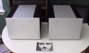
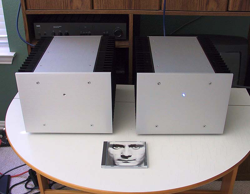
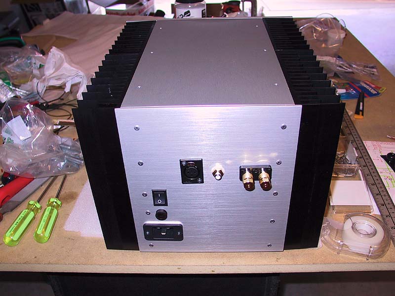
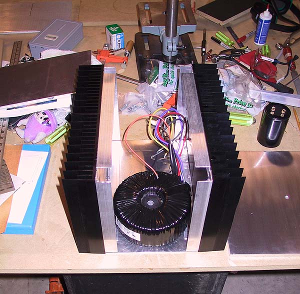
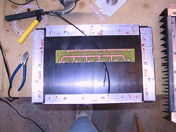
The chassis is the largest part of the project because you’re most likely not going to be able to go out and buy a chassis that can reject 300W of heat with no fan and without destroying your transistors. If you can find such a beast, buy it. Actually, buy 2 of them. I wanted my finished chassis to have a high quality, clean, professionally built look, and I think I finally achieved that. The “look” is along the lines of the clean Classe/Levinson/Krell boxes. The entire sides of the amps are heatsinks, the front is a 3/8” thick chunk of brushed and clear anodized aluminum, and the top is also brushed, clear anodized aluminum. I didn’t care too much about the backs or the bottom faces of the chassis, but I ended up getting the backs also brushed and clear anodized, and the bottom I left unfinished. The fronts have a very clean look - 4 chrome cap head bolts and a single power indicator blue LED. The power switch is on the back of the amp. I may get some lettering applied to the amp front plates in the future, and I may even look into getting the fronts engraved as an alternative - similar to the beautiful Classe Omega series machines.
Each of the amps weighs 42 lbs, so they’re fairly substantial but not so heavy that they are very difficult to move. The chassis have been bolted together in a solid enough manner that they feel quite strong and stiff - they don’t flex at all when being moved.
The heatsinks are really the heart of the project, and if you build a Class A amp, you’re going to spend some time and money getting this part of the project dealt with. After a lot of looking at web pages and catalogs, I finally found a local supplier who could supply sinks that were about half as wide as what I needed at a reasonable cost. The “half as wide” part is not a problem as you can just get two per side and join them together.
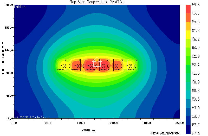
I did some thermal sims using the Aavid Thernmalloy website calculator on one of their sinks when I was trying to find a suitable sinks. The sinks I ran the sims on were roughly equivalent to the ones I eventually bought. The sims told me that my amps would have junction temps on the order of around 95C to 100C with a 78F ambient, and using the “touch test” I believe that the actual heatsinks I have are running a bit cooler than that. I haven’t measured the thermal profile of the amps yet, although I intend to do that one day. Also, the sims don’t take into account heat that the top, front, and back are pulling from the sides so there are several inaccuracies to the sims. The sims were very helpful though as a tool to size the sinks. For my amps, I ended up with amp sides that are about 14” wide, 9” high, the fins are 2” long, and the base plate thickness is 0.200”. If the fins are about a half inch to an inch apart, that will do well. Any more heatsinking would be a bonus in lowering the junction temps.
In my amps, he temps are good enough that I am not concerned about the junction temps. The hottest exposed part of the heatsinks is quite warm to the touch, but certainly not high enough to cause a burn. A small child would probably perceive it as quite warm though and would want to touch it maybe once and then leave it alone...
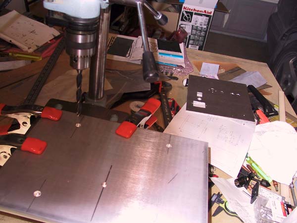
The rest of the chassis consists of simple plates of 6061-T6 aluminum. The top, bottom, front and rear panels were cut to size by the metal vendor, then I did the machining, then I sent them to a shop to be brushed and clear anodized. I’m very happy with the result. The boxes look like they were made by a high end manufacturer. I joined all the faces of the chassis together with 1”x1”x 1/16” aluminum angle extrusions on the inside of the box, and held them together with machine screws and pop rivets. When doing the drilling of the chassis parts, I made simple jigs to hold the pieces steady and used clamps to hold them in place. All drilling was done on a drill press. The resulting fit and finish turned out very well, so using methods like this will help immensely if you follow a similar method. Clecos are a boon to this process; they are worth their weight in gold.
The Main Board
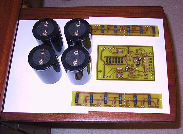
I divided the circuitry physically so that the “hot” parts would be located at the heatsinks, and the rest of the electronics went onto a single 4x6 PCB in each amp, the same as others who have built amplifiers. My boards were shameless copies from Mark Finney’s boards with a few exceptions, and I was happy to have Mark’s artwork to use as a starting point - it saved me a lot of time and effort. I got rid of the jumper that is on his design, made 45 degree bends instead of 90 degrees, and customized the spacing for the parts that I bought. I fattened up the traces that carry the current from the current source to the single ended drive, the output node between all the 0.5 ohm resistors, and the ground trace around the board. I also used 7 resistors of 0.5 ohms instead of 6 resistors of 0.47 ohms so I have space for 7 resistors in that position (those resistors can be 2 watt rated, you don’t need 5W parts there as they aren’t dissipating that much heat even when the amp is on a tear). I also bypassed the 220 uF cap on the inverting balanced input with a 0.1 uF film cap. Other than those two small part mods, the circuit is right out of the A2 manual. If I could go back and do this all again, I’d add around 3300 uF or 10000 uF of additional power supply filtering bypassed with maybe 10 uF film cap right on the main boards.
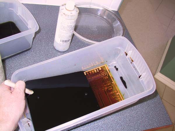
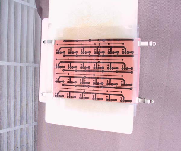
The boards themselves are quite easy to make. I used the positive presensitized single-sided PCBs you can get at Mouser or DigiKey since they are very easy to produce. I used a 6”x9” board with two panels (two copies of the artwork on a single physical board), then cut the panels after the board was exposed and etched. Do use a darkroom to get your artwork aligned onto the board before exposing. Also, double up your artwork on two transparencies and then tape the transparencies together - if you don’t do this, the traces will get exposed a bit and your boards won’t work out very well. You’ll need a piece of glass to hold the artwork firmly to the surface of the board. Don’t forget to expose the board “backwards” - put some letters on the artwork, then before exposing ensure you can’t read them properly looking at the copper side before exposing. I used the sun to expose the boards, 4 minutes works great. I just used a laser printer to make the art-work, but it comes out too light and you’ll need to double it up. Oddly enough the design was done using a program called Framemaker, which is a publishing package, but any drawing tool that can print to a laser printer will work. Once you’ve successfully made a couple PCBs, you will realize that basically the entire world of electronics has been opened to you.
Heatsink Boards
I also made some boards to wire up the high current portions of the amps. It saves a lot of effort over point-to-point wiring. To reduce problems here with resistive drops I used 2 oz copper on the boards. It seems to work fine. I actually made different boards - one for the left of the amp with the negative rail, and one for the right of the amp with the positive rail. The only difference is the point where the wiring points are - they are biased towards the rear of the amp because that’s where the main board is that the connections are made to. Again, I used a 6”x9” single sided board and this time it had 4 panels oriented along the long dimension. It was tight, but the panels all “just” fit.
If I was able to do this part of the project over again, I’d consider using 2 - 2W, 2 ohm resistors in parallel rather than the 5W 1 ohm resistors I did use and which are on the circuit schematic. It probably wouldn’t matter very much, but the net effect of this would be to reduce the parasitic inductance of the wire wound resistors. I don’t know what the inductance of the 2W resistors is compared to 5W ones though so I’d want to investigate that before actually making the change.
General
My building constraints are different from DIY’ers who are trying to produce a great product at an absolute minimum cost. I tend to use premium components, and this raises the cost somewhat. I also buy all the components new, rather than going through surplus parts as some others do. I’m not knocking the practice, but am merely noting that part of the DIY game is that everyone’s constraints are a little different and that leads to different project results.
I used all Cardas wires in this project, with the exception of the 120 VAC wiring and the 10 ga wires I used to connect the rectifier outputs to the power supply filter caps. The Cardas wire is awesomely difficult to work with if you can’t tin the ends properly. Fortunately, making a solder pot in order to tin the ends is rather easy. I just bought a cheap thick threaded metal pipe cap - the type used for gas or plumbing, a roll of 50/50 solder, some flux, and a propane cylinder for the torch I already had. You might consider going with 60/40, but the 50/50 worked fine. First get the wires cut to length and stripped on the ends. Then you arrange to hold the cap upside down securely, creating the “pot”, melt the solder into the cap, let it heat up another couple minutes, then dip the stripped and fluxed wire ends into the molten solder for 4 or 5 seconds, and voila, no more tinning problem with Cardas wire.
Please ensure that the “pot” is clamped securely before turning into a pyromaniac. Having 10 or so oz of molten solder poured on the floor is going to cause at least a difficult mess to clean up, and at worst it may burn your house down or cause you or someone you love a massive and incredibly dangerous burn. If you do that, I don’t want to know about it. You’ve been warned. It’s dangerous to have a large amount of molten solder lying around.
I also used all Cardas quad eutectic solder. I really like this stuff - it melts at a low temp, it flows really well, and I never get cold solder joints. Welborne Labs carries it in small quantities, it’s not too expensive if you buy a bit of it.
For the RCA connectors and binding posts, again the nod went to Mr. Cardas. They are very nice pieces. (No, I don’t get any freebies from Cardas, I just think I can’t go wrong if I’m using his products. They are all very high quality in material, fit, and finish. I’ve never had a problem with any of them.) I used the black metal Neutrik XLR connectors for the balanced inputs. All of these high end parts can be ordered from the (new) “Parts Connexion”.
For the indicator lights, I have some “real” blue LEDs (as opposed to white LEDs with blue lenses). These things can light up half the planet with 10 mA of current. I’m at 2.0 mA now (22k load resistor) and still need to maybe go to 1.0 mA to keep from lighting up my living room. You’ll need to experiment with this a bit probably also, but even 2.0 mA is too bright for my liking at night in a dark room.
I have some very nice Schurter 20 amp IEC shielded and filtered connectors, and used Nichicon 22,000 uF, 63V, “Super Through” filter caps which I was able to get as a favor through a local supplier. I used Plitron 1000VA toroids with 33+33V secondaries, this gives about 46 VDC on the power rails. The toroids are big and heavy and don’t make much mechanical hum. Nelson advised me that 1500VA would be even better so you may want to go with the larger donuts if you build an A2. I bought some plainjane power 14 ga power cords to connect to the 20 amp IEC plug from Digikey. Nothing special on the power cords yet, I think Nelson has written that he can’t tell the difference between power cords with the amplifiers so I’m not going to bother with it for now. I may try some shielded cable some day but it’s low down on my list of things to experiment with. I just have thick rubber feet on the bottoms of the amps for now, but will try some cones soon to see if I can tell the difference.
Upcoming
I think I zapped one of my blue LEDs because it has a light that doesn’t light on one side. I tested it after connecting to its wires, then cemented it into its hole in the front faceplate before assembling the amp. At any rate, the only problem I had turning up the amps was a dead LED.
I have a small amount of 60 cycle hum in my amps. It may be nothing, and I’ve heard many amps that are louder when “silent”. However, I can hear hum from maybe 6” from the speaker when at idle. It is certainly far too low to hear when in the listening position, and the amplitude of the hum doesn’t increase with the volume. I’m probably being overly critical here. I may try to put a cop-per strap around the outer circumference of the toroids to see if that reduces the hum.
Suppliers
• http://www.mouser.com - general parts, high quality Vishay/Dale resistors
• http://www.digikey.com - general parts
• http://www.partsconnexion.com - high end audio enthusiast parts
• http://www.wellbornelabs.com - high end audio enthusiast parts
Postsript
About myself - I’ve been a digital designer since graduating with a EE degree a long long time ago. I built a Bride if Son of Zen a year ago, and that was my introduction to the Pass designs and also high end DIY audio. I learned from that project that a high resolution audio system can be built if you have the time and patience and the training or aptitude. I bought the PCBs and chassis for the BoSoZ project, which limited its scope to a manageable size for a beginner. Thus I had a good foundation on which to build in order to bring the amplifier project to a successful completion. If you don’t have a background such as this, it’s probably not that large of a barrier as long as you are mechanically inclined and can obtain information from the web. There are quite a number of articles on the A series amps, and many are right here on the Pass Labs website.
About my system - so far
• Classe CDP.3 CD player - simple, clean sound with lots of features for its price
• DIY Bride of Son of Zen preamp
• DIY Custom speakers with Focal drivers
• Cardas Crosslink interconnects
• Axon 8 speaker cables • DIY A2 monoblocks