Miscellaneous Projects
I think the original idea for the ‘wall amp’ was to present the A-75 as an ‘instrument,’ something that looked like it was capable of producing the music. Speakers get to look like something, but the power amp is usually relegated to the status of a black box with wires leading in and out. I wanted to reveal some of the circuit, especially the A-75’s massive output section. As a design person, I like the repetition of the 48 MOSFETs in the output section. The TO3 cases used for the output devices are probably on the way out, to be replaced by ugly little plastic cases–sorry, but they just don’t have much visual appeal, as efficient as they are to manufacture. There is a good supply of large, older MOSFETS at Rochester Electronics, a company that takes pride in being on the trailing edge of technology.
I had already put together one incarnation of the Pass/Thagard A-75 (see Audio Electronics Four: 2000), I wanted to put more effort into giving this one a distinctive appearance as well as a great sound. I was pretty confident about the circuit and felt free to splay it out against the wall. The A-75 is a great project for anyone who wants a big ‘meaty’ amp without having to dish out thousands of dollars (OK, so it’s a thousand Canadian dollars with all the nice brass and acrylic).
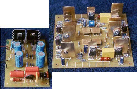
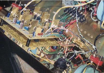
By the time I put together the power supply and driver cards (PCBs available at Old Colony Sound Lab), I had decided that brass would be a major theme; hence the small brushed brass heatsinks on the driver card.
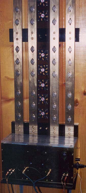
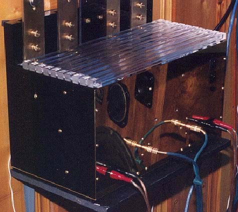
The guts of the wall amp are placed in a black acrylic enclosure with a brass face plate and bottom. An acrylic back plate supports the lower ends of the four brass bus strips on which the output MOSFETs are mounted. The two toroidal transformers from Plitron are also mounted on the back plate (62v. 300VA each). The bus bars, output Mosfets and transformers, about 90% of the 70 pound weight of the amplifier, are within one plane and basically all within an inch of the wall. The amplifier sits on a very small shelf with two small screws through the top support to stop it from rotating forward and falling down.
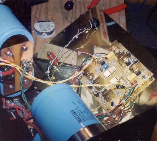
The driver card for both channels is mounted behind of the polished brass face plate. (Curious about Nelson Pass’ comments regarding feedback or none, I mounted two 5 meg potentiometers in place of the R81 resistors. They are accessed through two small holes in the faceplate and I can now adjust the amount of feedback. So far, I have not come to any firm conclusions, but I think I get a better bass when R81 is set to 0 ohms–more feedback.) The faceplate is hinged for easy access to the interior of the enclosure. The rest of the inside space is occupied by the four 40,000 micofarad capacitors used to filter the output stage power supply. The regulated 50 volt supply for the driver stage is mounted between the transformers on the back plate.
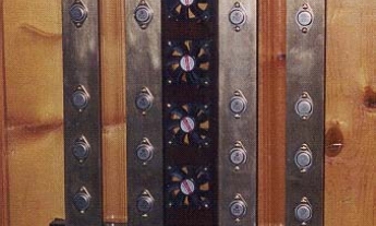
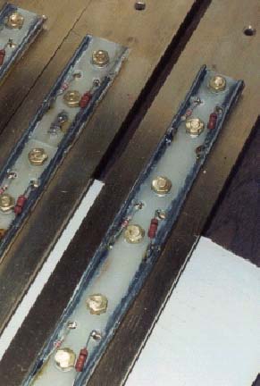
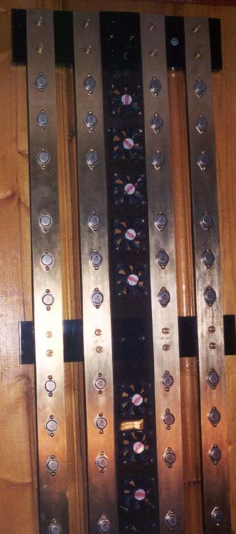
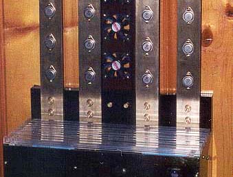
The output stage MOSFETs are mounted directly onto four 1/4" x 2" brass bars, each four feet long. These are supported by the back plate and two acrylic spacers. The bars are thermally isolated from the acrylic by nylon spacers beneath the bars and nylon washers on the bolts that fix them. The knurled nuts on the face of the bars reinforce the appearance of turn-of-the-century electrical gear. When the amp is operating, the bars are quite warm (50 0 - 60 0 C) and carry a 90-volt potential.
The gate and source resistors are mounted on long sections of circuit board attached to the back of the brass bus bars. Two lengths of heavy copper wire soldered to the edges of the boards hold the sections together and act as ‘rails’ for the gate and source. The third conductor is the bus itself, which supplies voltage to the drain of each MOSFET.
The 10 small cooling fans are mounted in a strip of smoked acrylic in the center of the heat sink. Air is drawn in at the center of the heat sink and exhausted between the bars on each side. The size of the bars and high specific heat of brass means that cooling does not have to be terribly even. The 12-volt fans run at about 5.5 volts, about the minimum at which they will self-start. Even at this reduced speed, they still make a distinct fan noise when the amp is running. I don’t listen to any music that is quiet enough to hear the fans, so this isn’t a problem for me. I’m fairly addicted to dance music with a heavy bass line.
The top cover of the enclosure is made from ½" clear acrylic bars. Acrylic is really easy to cut, bend and join. It is also a material with a 100+ year life span ac-cording to the U.S Navy (http://www.naut-resguild.org/weg-long.html) As can be seen from the photograph, the translucent top allows a partial view of the interior and can be easily lifted off for an unobstructed view of the amplifier guts.
When one considers some of the features desired in a power amplifier, portability should be way down the list–after all, how often do you move? This one is clumsy to handle and moving it safely takes two people–and enough foresight to discharge the filter capacitors before attempting it.
This is a lovely sounding amp that has really underscores my need for a better set of loudspeakers. It was fun to build, and whatever the merits of the design, something intriguing to look at, listen to, and talk about.
Again, thanks to Nelson Pass and Norm Thagard for a design that just won’t go away.
Thanks to Mick at Ranger Audio in Calgary for final adjustment and testing.
Julian Evetts
Calgary, Alberta