A75 Part 2
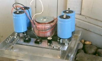
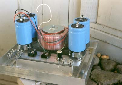
This A75 has an all-aluminum chassis. Shown here, the base with Hammond 550 watt torroidal transformer and other power supply components mounted. The slots on the bottom allow air to circulate around the transformer and cool the rectifiers. The completed case is exhausted by 2 small fans mounted in the top of the amplifier. The entire chassis was built with a hacksaw and 1/4 inch hand-held drill it was the hardest part of the whole project. I took Hammond at their word when they said that torroidal transformers don’t radiate. I mounted the transformer bare with no pot. It does not hum.
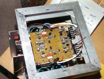
The 50 volt regulated power supply sits between the capacitors for the 40 volt unregulated supply. It is mechanically fastened by the same bolt that holds the transformer. I’m impressed by really neat wiring, but seldom achieve it.
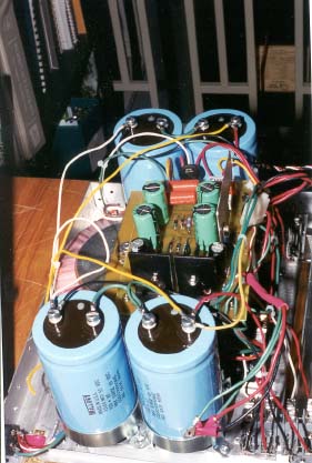
The driver section of this A75 mounts on the top frame of the chassis. Together with the post which holds the input and output connections, it can be removed and operated independently (I wanted to be able to separate it from the power supply in case I had to troubleshoot any AC hum.) Although not shown here, the first two output mosfets for each channel are also mounted on the ‘post’. The amplifier was started using only the first output pair on each side, with the rest of the output stage ‘wrapped’ around the case later.
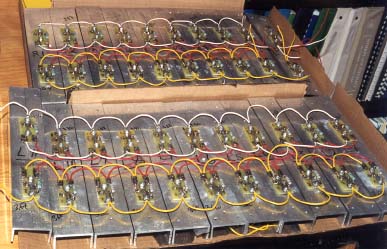
I ‘hand drew’ the circuit boards using a resist crayon. This is an extremely uncritical design and seems to be unaffected by my ‘artistic’ interpretation of the original board layout. Board shown here is nearly finished, missing only input pairs on both channels.
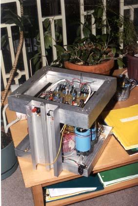
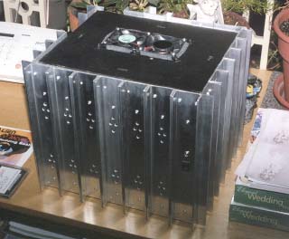
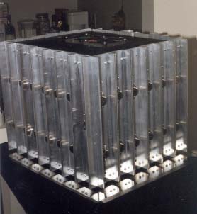
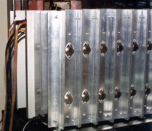
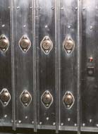
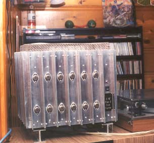
The heatsinks for the output stage are mounted around the outside of the case. The case is shown here fitted and assembled without mosfets. Note the fans in the top plate scavenged out of a couple of old 486 computers that couldn’t make the Y2K cut. These fans have since been moved to the bot-tom of the case and blow air in from the bottom. I found that the top mounted fans prevented the driver card from warming up evenly. Later, the output mosfets were mounted using small boards which hold the source and gate resistors. Each side can be assembled and tested as a unit before mounting on the case. As Vlatko Cvic pointed out in his article in the August 99 issue of Audio Electronics, drilling all the mounting holes is a real chore. (500 precisely placed holes to mount the 48 output mosfets and heatsinks on this amp)
The linear lay-out of the output makes me think that the next version of this amp I build will be a flat, wall-mounted unit . . .
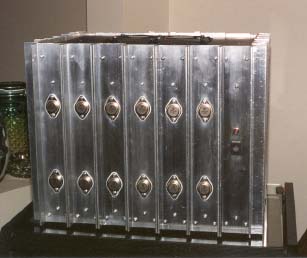
Back of the A75 showing the ‘post’ with input/output connectors This design offers some 2000 square inches of surface area, and a lot of thermal mass. It seems to shed heat well. Operating temperature rises to 50 0 C and doesn’t rise more than a couple of degrees when the volume is turned up . . . and we do turn it up. At some point I will try it without the top cover and fans to see if convection alone will cool it. AMP90.
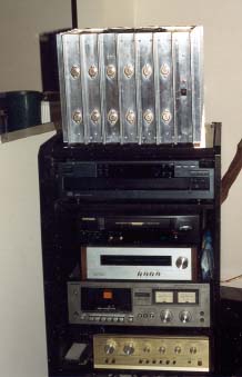
The finished amplifier has internal dimensions of 12" x 13" x 12" The fins on the heat sinks add another two inches to the length and width on the outside. The A75 is shown here sitting on top of the stereo stand and being driven by the Dynaco PAT 5 (assembled in 1972 and still sounding fine) at the bottom of the picture. This A75 will eventually be placed at the bottom of the stand, behind glass to keep folks from touching it.
The sound quality on this amp is exceptional. Music is nicely defined; solid stereo image; and a depth that some of my friends compare to Sugden or Quad . . . I’m certainly impressed.
Thanks to Nelson Pass and Norm Thagard for designing this puppy and making it available to people like me.
Thanks to Audio Amateur/Audio Electronics for publishing the original articles describing this amp, and Pass Labs for keeping it posted on their website.
Thanks to Ranger Audio, Calgary for final adjustment and testing.
Julian Evetts,
Calgary, Alberta
One Year Later . . .
After a year of operation (about 2000 hours in my house) this amplifier continues to perform well. I removed the cooling fans and allowed free airflow through the top by using a stainless steel mesh. The fans made some noise and were really not necessary.
AMP-NEW1 & 2.
My friends joke about my ‘steam-powered’ amp. It takes 30-40 minutes to get to operating temperature., but once fully warmed, it sounds great. Now connected to a Hafler solid-state preamplifier.
An edited version of this piece appeared in Audio Electronics 4/2000.....je