A40 Part Substitutions
First and foremost I'd like to thank you for all your contributions to the DIY community and the efforts you put forth to maintain a presence both through your website and on DIYaudio. The do it yourself world would be a lesser place without the work you've done.
I've included several pictures of my first attempt at one of your class A designs, namely the A-40 power amplifier in monoblock form. The circuit shown here has gone through three complete remakes before I was happy with it, and as you can see I've settled on an "all on one board" solution. I'll go through the pictures first, and then get to the details later.
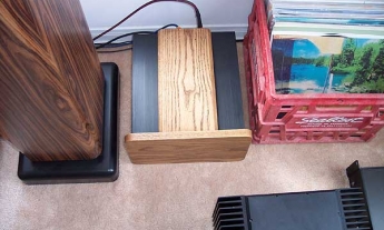
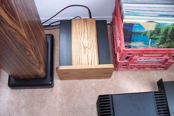
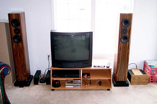
Photo 1: This is the complete A-40 amplifier sitting in its place in my current system. To the left are a pair of Lynn Olsen's Ariels, and to the right is the chassis for a future Aleph 2.
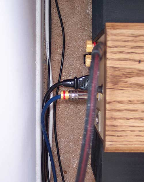
Photo 2: This is a rather poor picture of the rear panel, showing the location of the rear connections. The chassis were originally designed for an Aleph 5, which explains the XLR connector that isn't used in the A-40.
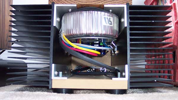
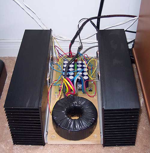
Photo 3: A shot of the inside of the chassis showing the power transformer (250 VA per channel), the power connections along the bottom at the back, and the circuit board with the transistors mounted off the sides. There are two transistors per side, spaced as far apart as I could get them. I used L-channel aluminum, MDF, and red oak for the chassis.
Photo 4: Here's the left channel still in "prototype" form with the transistors wired off board, and the connectors still hanging off the back. Not the safest setup, but the roommates have been warned.
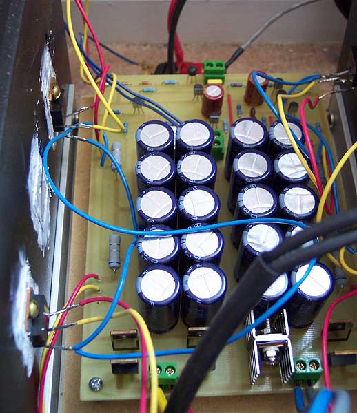
Photo 5: A closer shot of the PCB showing the temporary transistor mounting, the power supply capacitors, the diodes, and the low-level circuitry towards the back of the amplifier. The dual secondary taps of the transformer connect directly to the PCB, and the only other external connections are the input and the speaker output. I opted for several smaller capacitors en lieu of two giant caps. It saved space and allowed me to get a higher overall capacitance in a smaller space. The little heatsinks on the diodes were just an experiment which proved to be ineffective.
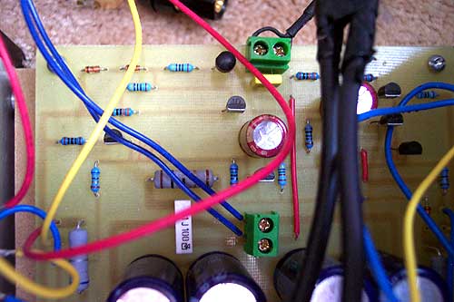
Photo 6: This view of the low-level circuitry shows the RCA input (top), loudspeaker output (don't laugh at the 20AWG blue speaker wire) and the Elna Cerafine capacitors in the signal section.
Photo 7: The two monoblocks (one finished, one not so much) in my current setup. The amplifier gain is high enough to allow me to use a single 24 step attenuator driven directly from my phono preamp or the crummy Toshiba DVD player. The turntable and preamp sit on a separate table to the right, and the volume control is the thing wrapped in electrical tape on the lower shelf (I have no shame). To the left are the bare boxes soon to be a pair of Thor loudspeakers.
The amplifiers have been in use for about three months now, and haven't had a single problem since I started them up. The heatsinks are overkill for such a small amplifier, and run at a comfortable 40-45 degrees C. I measured the AC input current using a Fluke RMS averaging meter and calculated about 140 watts of constant power draw from each channel. The output from both amplifiers is dead quiet, showing no signs of hiss even with an ear 1" away from the tweeter. The DC offset is well below 30 mV, and there really isn't any startup thump. I haven't seen any instability whatsoever, nor have I notice any susceptibility to power fluctuations.
I designed and etched the boards myself using Altium's Protel software and press'n'peel transfer paper. All the resistors are metal film and hand matched to 0.1%. The PS caps are standard Panasonic 3300 uF 35V with ten caps per channel per rail giving 33,000 uF per rail, or 66,000 uF per channel. The transistors are all to spec except for the output transistors where I used a complimentary pair of On-Semi's MJH6284/87 series Darlington power transistors. The J-FET in the CCS was just an old thing I had sitting around that happened to do the trick. The output transistors were chosen because their emitter resistor was the specified 25 ohms, and I wanted to avoid the TO-3 package style because of my heatsinks.
I love the sound of the amps and haven't run into any "lack of power" situations given that the speakers are about 92dB/1W/1M. The bass is excellent compared to my modified Dynaco ST-70, and the amplifier still maintains a very smooth midrange, which was a pleasant surprise for me. I've been a very strong tube advocate for years, but this amplifier seems to have all the advantages of any tube amp but with better bass, a more extended top end, and much more resolution.
Based on my experience with building these amps, I have three building tips for anyone looking to construct this or any of the other class A amplifiers:
1. Use BIG heatsinks. When you think you have enough, double that amount. 2. Use oversized toroids. Mine are 225VA, per channel, and they're the second hottest things in the amplifier. 3. Don't underestimate the rectifier diode dissipation, mine are by far the hottest things in the amplifier and probably should have been on a heatsink.
I'm looking forward to finishing the Aleph 2's mentioned earlier and comparing the two designs. I'm sending this in now so I can get my hands on those stickers for the Aleph's!
Thanks again for all your hard work and excellent designs; it's what made all this possible.
Cheers,
Owen Columbus.